ZTE / DC power systems

ZXD5000 (V6.0) Equipment information & support

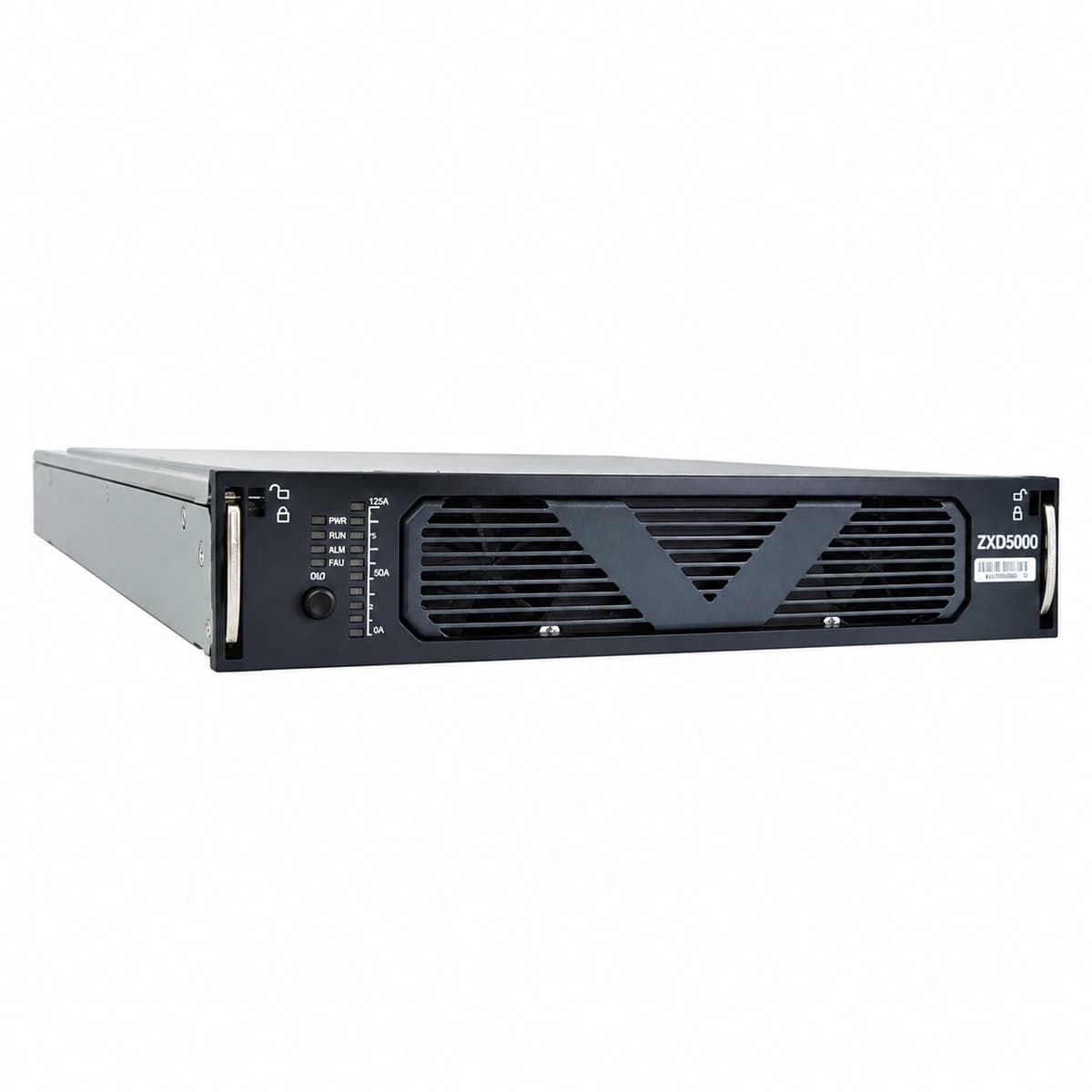
ZTE ZXD5000 (V6.0) is a massive 5000W (-48V/100A) digital switch-mode rectifier module engineered with active PFC for high-density central power plants.

Equipment information

Brand
ZTE
Equipment model
ZXD5000 (V6.0)
Equipment type
DC power systems
Controller / software version
Confirm against the installed equipment
View full product specifications
ZXD5000 (V6.0) Official Product View 1

Information below comes from the current product catalogue. Confirm the controller, software version and configuration of the installed equipment separately.

AC Input Voltage Range
80VAC ~ 300VAC single-phase (150V~300V full-load output) VAC
Nominal DC Output Voltage
-48 V DC
Cooling Method
Forced-air cooling and damage-free module hot-swap technology

Alarms & troubleshooting

AC_IN_FAIL (AC Input Failure / Phase Loss)
RUN LED (Green) OFF, ALARM LED (Red) Steady ON
AC mains power outage, phase voltage outside permissible range (<80VAC or >300VAC), upstream circuit breaker trip, or phase loss.
1. Verify that the upstream AC miniature circuit breaker (MCB) feeding the rectifier is closed. 2. Measure input terminal AC voltage across all phases using a digital multimeter (normal range: 85VAC to 295VAC). 3. Reseat the rectifier module firmly into the power subrack; if the fault persists, replace the rectifier module.
DC_OUT_OVP (DC Output Overvoltage Lockout)
ALARM LED (Red) Steady ON, DC output completely shut down
Internal voltage control feedback loop failure, corrupted CSU overvoltage parameters, or busbar external surge triggering hardware HVSD latch (>59.5VDC).
1. Remove the alarmed module and measure the DC busbar voltage with a multimeter to verify it is within normal float limits (53.5V to 56.4V). 2. Inspect the overvoltage protection threshold configured on the Central Supervision Unit (typically 58.5V to 59.0V). 3. Power cycle the module by keeping AC off for 3 minutes to discharge internal capacitors, then reseat; if it latches immediately into OVP, replace the rectifier.
OVER_TEMP (Module Over-Temperature / Derating)
RUN LED (Green) Slow Flashing (derating) or ALARM LED (Yellow/Red) Steady ON (shutdown)
High ambient shelter temperature (>55°C), clogged cabinet dust filter, blocked front/rear ventilation path, or degraded internal heatsink NTC sensor.
1. Check air conditioning operation in the equipment room and ensure ambient temperature is maintained between +15°C and +30°C. 2. Clean the cabinet air inlet dust filters and blow out dust from the module front bezel and heatsink. 3. Allow the module to cool down and verify automatic self-recovery; replace the rectifier module if false over-temperature alarms persist with normal airflow.
FAN_FAIL (Fan Stalled / Speed Fault)
ALARM LED (Yellow) Steady ON or Blinking, fan stationary or running at continuous 100% full speed
Worn fan bearing causing mechanical seizure, foreign object blocking fan blades, loose tachometer/PWM cable connection, or failed on-board fan driver IC.
1. Inspect the front air grille to ensure no cable ties, dust mats, or foreign debris are jammed in the fan blades. 2. Manually rotate fan blades while unpowered to confirm smooth mechanical spinning. 3. Disconnect and reseat the fan assembly connector on the front panel; if the alarm persists, replace the front fan tray or the rectifier module.
COMM_FAIL (CAN-Bus Comm Failure / Current Share Error)
RUN LED (Green) Flashing, CSU reports module offline while module supplies unmetered DC with >10% load unbalance
Degraded gold-finger CAN pin contact on the subrack backplane, improper CAN terminal resistor matching, ID conflict, or CSU polling timeout.
1. Verify the rectifier list in the Central Supervision Unit (CSU) to inspect slot mapping and baud rate negotiation. 2. Pull out the rectifier module, clean the gold-finger contacts using isopropyl alcohol, check for bent backplane pins, and re-engage the module lock. 3. Check the 120-ohm CAN bus termination resistor jumper on the power backplane; if adjacent modules communicate normally, replace the faulty rectifier module.

Access Complete Maintenance & Full Alarm Troubleshooting Manual

This page lists high-frequency critical alarm codes commonly encountered in field maintenance. Comprehensive manufacturer troubleshooting matrices, board-level repair guides, detailed electrical schematics, and firmware commissioning manuals are delivered alongside equipment upon formal project procurement, accompanied by dedicated FAE technical support.

Share on-site information

  1. 01

    Identify the exact model

    Record the nameplate, system model and controller or module model.

  2. 02

    Keep the alarm details

    Record the full alarm text, indicator colour, timing and whether it persists.

  3. 03

    Describe recent changes

    Note recent replacements, software updates or configuration changes.

Record information visible in the existing interface. Electrical measurements, disassembly and replacement should follow the applicable manufacturer's manual and be performed by qualified personnel.

Your model and these details will be added to the enquiry form for you to review before sending.

Related technical articles

Browse the technical guides or send a question about this model.

View all articles

Need a replacement module or supporting equipment?

Confirm the full model, system configuration and compatibility requirements before enquiring about suitable products.

Ask about suitable products

Have a model and an on-site issue?

Share the exact model, alarm text and observed symptoms to help identify relevant information and compatibility requirements.

Request technical support