ZTE / Outdoor power systems

ZTE ZXDU68 B301 2.1m Outdoor Cabinet System Equipment information & support

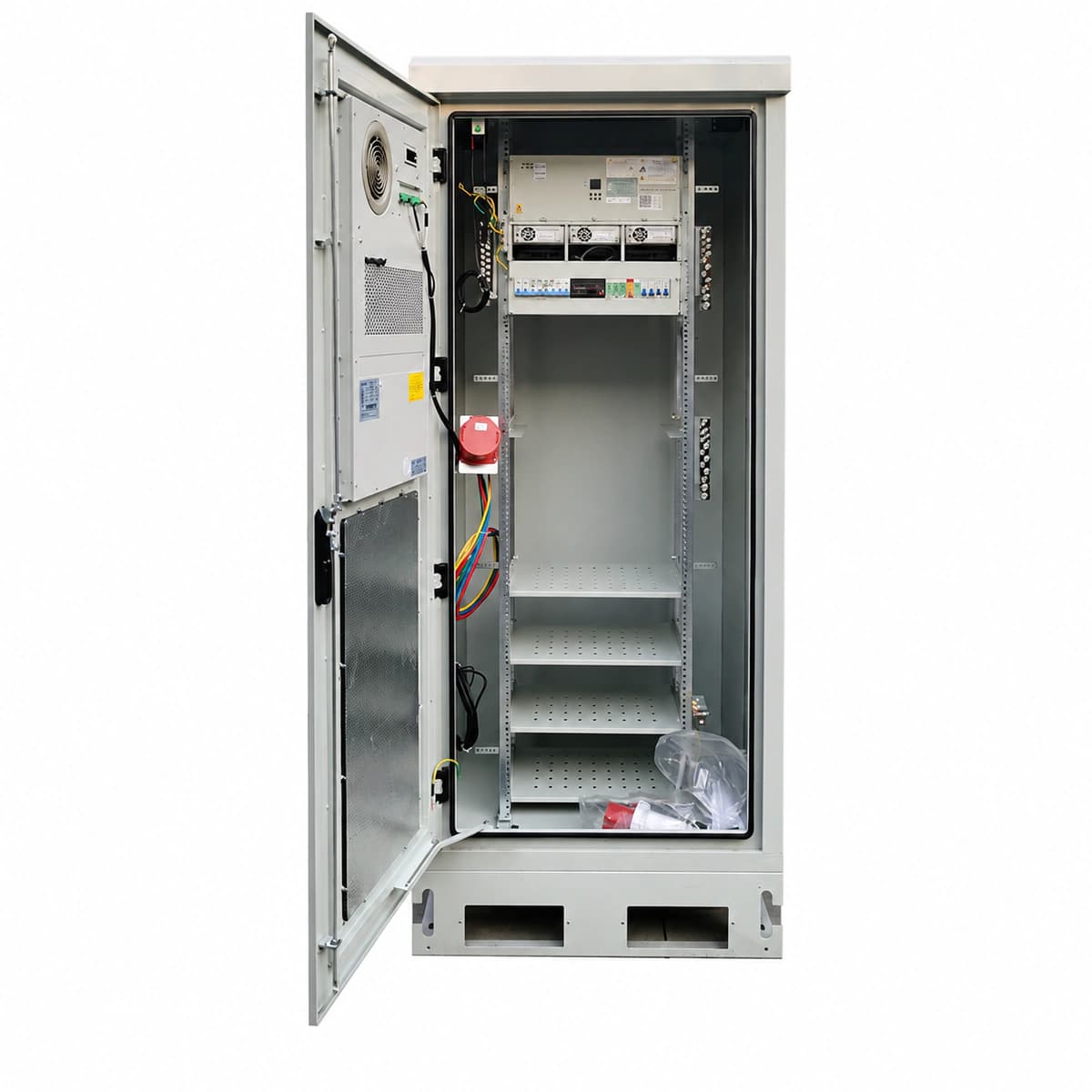
The ZTE ZXDU68 B301 is an industrial-grade 2.1m outdoor integrated telecom DC power cabinet system delivering sustained -48V 300A output with an IP55 dual-compartment structure, engineered for macro stations and harsh edge computing sites.

Equipment information

Brand
ZTE
Equipment model
ZTE ZXDU68 B301 2.1m Outdoor Cabinet System
Equipment type
Outdoor power systems
Controller / software version
Confirm against the installed equipment
View full product specifications
ZTE ZXDU68 B301 2.1m Outdoor Telecom Power Cabinet System -48V 300A IP55

Information below comes from the current product catalogue. Confirm the controller, software version and configuration of the installed equipment separately.

Cabinet Physical Height
2.1m Integrated Dual-Door Outdoor Telecom Cabinet (IP55 Sealed)
System Output Capacity
300A (-48V DC) Continuous Output Capacity
Heat Exchange Cooling System
Door-Mounted Plate Heat Exchanger + Roof Emergency Direct Ventilation
Controller System
CSU Intelligent Supervisory Unit with Graphical LCD
Rectifier Module Slots
6 Slots (Compatible with ZTE ZXD3000 50A Ultra-HE Rectifiers)
Two-Level LVD Protection
Supports Dual-Stage LLVD (Load Disconnect) & BLVD (Battery Disconnect)

Alarms & troubleshooting

AC_FAIL (AC Mains Power Failure / Phase Loss)
CSU ALARM red LED solid ON; Rectifier RUN green LED OFF
Mains blackout, AC input circuit breaker tripped, surge breaker open, or phase conductor loose causing voltage drop below 80 VAC.
1. Verify upstream distribution breaker and outdoor cabinet AC main input breaker status. 2. Measure phase-to-phase (304–456 VAC) and phase-to-neutral (176–264 VAC) voltages at terminal block using a calibrated DMM. 3. Tighten all input terminal screws and verify AC SPD circuit breaker status. 4. If voltage is nominal, inspect CSU AC sampling wiring harness and connector pins.
DC_VOLT_LOW_LLVD (DC Under-Voltage & LLVD Contactor Open)
CSU ALARM red LED solid ON; Audible buzzer active; LLVD auxiliary status indicator OPEN
Prolonged AC blackout; battery discharge reaches LLVD threshold (default -47.0 VDC) triggering contactor trip; or all rectifiers failed.
1. Connect a mobile diesel generator to the outdoor cabinet manual transfer inlet. 2. Check total load current and measure individual battery cell terminal voltages for short-circuited or reversed cells. 3. If emergency bypass is needed, manually override LLVD via CSU menu while monitoring battery deep-discharge limit (-43.2 VDC). 4. After AC recovery, verify that rectifiers auto-restart in boost charge mode and LLVD contactor re-closes.
REC_HVSD (Rectifier Output Overvoltage Hardware Lockout)
Faulty Rectifier ALARM red LED solid ON; RUN green LED OFF; CSU LCD indicates Rectifier Fault
Internal DC/DC pulse-width control failure causing DC voltage to exceed hardware threshold (58.5–60.0 VDC), or transient surge on current-share bus.
1. Identify the slot location of the faulty rectifier and switch off its dedicated AC input breaker. 2. Unlock the front handle, slide the module out by 10 cm, and wait 3 minutes for internal DC link capacitors to discharge. 3. Inspect the rear gold-finger blind-mate connector for arc burns or debris, re-insert firmly, and close the breaker. 4. If the red LED re-engages and locks out within seconds, the internal MOSFET/IGBT or control loop is defective; replace with a spare ZXD3000 module.
REC_FAN_FAULT (Rectifier Cooling Fan Stalled / Tacho Error)
Rectifier ALARM red LED blinking (1Hz); CSU displays Module Fan Alarm with thermal power derating
Dust/debris ingestion in outdoor environment seizing fan blades, bearing failure, or tachometer feedback PWM signal loss.
1. Inspect the rectifier front airflow grill for dust buildup, insect ingress, or physical obstruction. 2. Clean the heatsink tunnel and fan blades using an ESD-safe brush and dry compressed air. 3. Spin the impeller gently by hand to test for mechanical friction or frozen bearings. 4. If the fan fails to spin or PWM error persists upon power-up, replace the plug-in DC fan assembly.
SPD_ALARM (Surge Protective Device Degradation / Fault)
CSU ALARM amber LED solid ON; SPD mechanical status flag turned from Green to Red
Cabinet subjected to direct lightning transient or severe line surge, blowing out MOV elements; or remote signaling dry-contact wiring loose.
1. Inspect the AC and DC surge suppression sub-racks inside the outdoor cabinet to spot the module with a red visual inspection window. 2. Verify the SPD backup circuit breaker status and test remote signaling dry-contact continuity with a multimeter. 3. Turn off the SPD circuit breaker, pull out the blown plug-in MOV cartridge, and insert a genuine replacement unit (e.g., Class II 20kA/40kA). 4. Confirm the inspection flag shows all green, reclose the SPD breaker, and verify that CSU clears the alarm automatically.

Access Complete Maintenance & Full Alarm Troubleshooting Manual

This page lists high-frequency critical alarm codes commonly encountered in field maintenance. Comprehensive manufacturer troubleshooting matrices, board-level repair guides, detailed electrical schematics, and firmware commissioning manuals are delivered alongside equipment upon formal project procurement, accompanied by dedicated FAE technical support.

Share on-site information

  1. 01

    Identify the exact model

    Record the nameplate, system model and controller or module model.

  2. 02

    Keep the alarm details

    Record the full alarm text, indicator colour, timing and whether it persists.

  3. 03

    Describe recent changes

    Note recent replacements, software updates or configuration changes.

Record information visible in the existing interface. Electrical measurements, disassembly and replacement should follow the applicable manufacturer's manual and be performed by qualified personnel.

Your model and these details will be added to the enquiry form for you to review before sending.

Related technical articles

Browse the technical guides or send a question about this model.

View all articles

Need a replacement module or supporting equipment?

Confirm the full model, system configuration and compatibility requirements before enquiring about suitable products.

Ask about suitable products

Have a model and an on-site issue?

Share the exact model, alarm text and observed symptoms to help identify relevant information and compatibility requirements.

Request technical support