ZTE / DC power systems

ZTE ZXDU68 B201 Equipment information & support

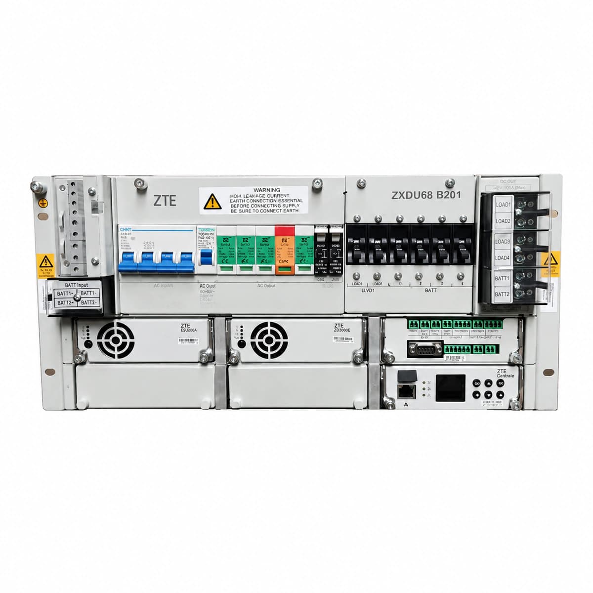
The ZTE ZXDU68 B201 is a compact 5U 19-inch rack-mount embedded DC power system delivering 200A continuous power at -48VDC across 4 high-efficiency ZXD3000 rectifier slots, integrated with built-in AC/DC breakers and an advanced CSU502A supervisory controller.

Equipment information

Brand
ZTE
Equipment model
ZTE ZXDU68 B201
Equipment type
DC power systems
Controller / software version
Confirm against the installed equipment
View full product specifications
ZTE ZXDU68 B201 Official Product View 1

Information below comes from the current product catalogue. Confirm the controller, software version and configuration of the installed equipment separately.

Nominal Output Voltage
-48 VDC
Output Voltage Range
-42 ~ -58 VDC
System Comprehensive Efficiency
> 96.0%
Ingress Protection (IP Rating)
IP20 embedded 5U rack-mount design
System Monitoring Controller
CSU502A / CSU500B intelligent monitoring unit
Physical Dimensions Spec
222 × 482 × 360 mm (5U 19-inch)

Alarms & troubleshooting

AC_FAIL (AC Mains Failure / Phase Loss)
CSU ALM LED red solid; Rectifier AC LED off, ALM LED red solid
AC input circuit breaker tripped; grid blackout, severe undervoltage (<80Vac), or phase loss; upstream AC SPD circuit breaker opened
1. Measure phase-to-phase and phase-to-neutral voltages at the AC distribution terminal blocks using a multimeter. 2. Inspect upstream distribution breakers and verify if the AC SPD surge indicator has turned red. 3. Ensure all rectifier AC branch breakers are securely closed with no loose terminal wiring. 4. If mains voltage is verified within nominal range, inspect the CSU AC voltage sampling terminal and wiring harness.
DC_OVP_LOCK (DC Output Overvoltage Lockout)
Rectifier RUN LED off, FAULT LED red solid (locked), CSU indicates high voltage alarm
Rectifier internal PWM regulation fault causing bus voltage to exceed 58.5V/59V, triggering secondary hardware overvoltage lockout
1. Trip the AC breaker of the faulty rectifier module, pull it out slightly, and wait 3 minutes to discharge internal capacitors. 2. Measure the DC bus and battery terminal voltages with a multimeter to confirm system voltage is normal (-53.5V to -54.5V). 3. Reseat the module, close the AC input breaker, and observe if overvoltage lockout recurs. 4. If the FAULT LED remains red and no output is produced, the internal circuit is defective; replace the rectifier module.
REC_COMM_FAIL (Rectifier CAN Bus Comm Failure)
CSU displays module offline/cross mark; Rectifier RUN LED flashes rapidly (2Hz); CSU ALM amber
Poor contact or oxidation on backplane gold finger CAN pins; loose CAN ribbon cable; missing termination resistor; damaged transceiver chip
1. Unseat the rectifier, inspect rear edge connector pins for bends, burn marks, or dust, clean with contact cleaner, and firmly reseat. 2. Check the CAN ribbon cable connecting the backplane to the CSU; reseat both ends securely. 3. Navigate to the CSU system menu, verify module ID addressing, and execute the 'Rectifier Search / Auto-Register' command. 4. Swap the module into an adjacent known-good slot; if the issue follows the module, replace the rectifier unit.
REC_TEMP_HIGH (Rectifier Internal Over-Temp Shutdown)
Rectifier ALM LED amber/red solid; internal fan runs at max RPM or stalled; output power derates to 0A
Cabinet dust filter clogged blocking airflow intake; rectifier integrated DC fan stalled or failing; ambient room temp exceeds +55°C
1. Remove and clean the front cabinet door air dust filter and air grilles. 2. Inspect the air channel and front intake of the alarmed rectifier using a flashlight to clear any lint, debris, or dust. 3. Check airflow and fan rotation; if the fan is stalled, making abnormal noise, or not rotating, replace the fan assembly. 4. Verify site HVAC operational status, ensuring air inlet ambient temp drops to +20°C to +30°C; the module will auto-recover once cooled.
BLVD_ACT (Battery Low Voltage Disconnect Active)
CSU ALM LED red solid, buzzer sounding; BLVD DC contactor physically open/tripped
Prolonged AC mains outage with no rectifier output, batteries fully depleted to BLVD threshold (typically -43.2V); faulty contactor coil driver; incorrect voltage parameter set in CSU
1. Connect an emergency mobile generator or restore AC power to allow rectifiers to power the DC bus. 2. Once mains is restored and DC bus reaches >-48V, execute a 'Manual Force Close BLVD Contactor' command in CSU if it does not automatically reconnect. 3. Measure the voltage across the contactor drive coil; if control voltage (-48V) is present but mechanical contacts do not close, replace the DC contactor. 4. Check the CSU configuration to verify that the BLVD disconnect threshold is properly configured (standard is -43.2V) to avoid premature tripping.

Access Complete Maintenance & Full Alarm Troubleshooting Manual

This page lists high-frequency critical alarm codes commonly encountered in field maintenance. Comprehensive manufacturer troubleshooting matrices, board-level repair guides, detailed electrical schematics, and firmware commissioning manuals are delivered alongside equipment upon formal project procurement, accompanied by dedicated FAE technical support.

Share on-site information

  1. 01

    Identify the exact model

    Record the nameplate, system model and controller or module model.

  2. 02

    Keep the alarm details

    Record the full alarm text, indicator colour, timing and whether it persists.

  3. 03

    Describe recent changes

    Note recent replacements, software updates or configuration changes.

Record information visible in the existing interface. Electrical measurements, disassembly and replacement should follow the applicable manufacturer's manual and be performed by qualified personnel.

Your model and these details will be added to the enquiry form for you to review before sending.

Related technical articles

Browse the technical guides or send a question about this model.

View all articles

Need a replacement module or supporting equipment?

Confirm the full model, system configuration and compatibility requirements before enquiring about suitable products.

Ask about suitable products

Have a model and an on-site issue?

Share the exact model, alarm text and observed symptoms to help identify relevant information and compatibility requirements.

Request technical support