ZTE / DC power systems

ZTE ZXDU48 B900 Equipment information & support

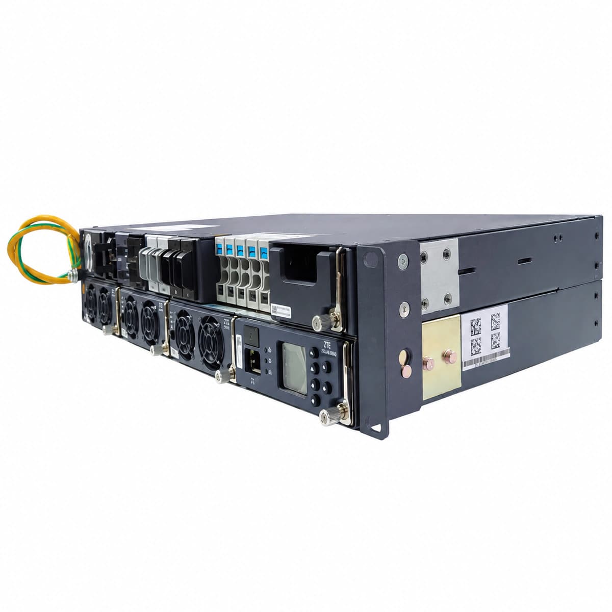
The ZTE ZXDU48 B900 is a compact 3U 19-inch rack-mount embedded DC power system engineered for access nodes and micro base stations, delivering up to 90A at -48VDC across 3 rectifier slots with integrated AC/DC breakers and a CSU401S controller.

Equipment information

Brand
ZTE
Equipment model
ZTE ZXDU48 B900
Equipment type
DC power systems
Controller / software version
Confirm against the installed equipment
View full product specifications
ZTE ZXDU48 B900 Official Product View 3

Information below comes from the current product catalogue. Confirm the controller, software version and configuration of the installed equipment separately.

Nominal Output Voltage
-48 VDC
Output Voltage Range
-42 ~ -58 VDC
System Comprehensive Efficiency
> 94.5%
Ingress Protection (IP Rating)
IP20 compact 2U/3U rack-mounted
System Monitoring Controller
CSU401S compact monitoring unit
Physical Dimensions Spec
132 × 482 × 290 mm (3U 19-inch)

Alarms & troubleshooting

AC_FAIL (AC Mains Power Failure / Loss)
CSU ALM LED solid red, Rectifier IN LED off, Rectifier ALM LED solid red.
Mains utility outage, tripped AC circuit breaker, input phase loss, or AC voltage below rectifier operating threshold (<80VAC).
1. Measure line-to-line and phase voltages at the AC distribution box to verify grid supply.\n2. Inspect the ZXDU48 B900 AC input circuit breakers and surge protection breakers; reset if tripped.\n3. Check the AC surge protection device (SPD) window for failure or short circuit.\n4. Once AC supply is restored, verify that rectifier IN indicators return to solid green.
DC_HVSD (DC Bus Overvoltage Hardware Shutdown)
Faulty rectifier ALM LED solid red, RUN LED off, CSU displays Rectifier HVSD alarm.
Internal PWM loop failure, damaged voltage sampling circuit in rectifier, or bus voltage exceeding hardware threshold (59.5V DC), triggering self-lockout.
1. Unseat the flagged rectifier module and allow internal capacitors to discharge for 3 minutes.\n2. Measure the actual DC bus voltage with a DMM; verify CSU float (53.5V) and equalize (56.4V) settings.\n3. Re-seat the module and monitor startup. If it immediately triggers HVSD and locks out, replace the rectifier.\n4. Verify current sharing balance across remaining modules to ensure no runaway voltage condition.
LLVD_ACT (Load Low Voltage Disconnect Active)
CSU ALM LED solid red, audible buzzer active, LLVD DC contactor open/de-energized.
Prolonged AC mains outage causing battery discharge below threshold (default 44.0V DC), triggering LLVD contactor drop to shed non-critical loads.
1. Connect an emergency generator or restore AC utility power to bring rectifiers online immediately.\n2. If grid recovery is delayed, force emergency reconnect via CSU menu 'LLVD Manual Close' (closely monitor battery EOD limit).\n3. Measure individual cell voltages to identify defective or weak battery blocks draining the bank.\n4. Once DC voltage rises above re-engagement threshold (~50.0V DC), verify LLVD contactor automatically pulls in.
RECT_COMM_FAIL (Rectifier CAN Communication Loss)
CSU reports module offline/communication interrupted, Rectifier yellow ALM LED blinks (0.5Hz), green RUN stays on (autonomous mode).
Bent or oxidized CAN bus pins on backplane connector, loose ribbon cable to CSU, termination resistor fault, or damaged CAN transceiver chip.
1. Remove the module; inspect backplane guide pins and connectors for damage or dust, clean and firmly reseat.\n2. Check the communication cable harness between the subrack backplane and the CSU controller.\n3. Measure resistance between CAN-H and CAN-L across the bus with power isolated (nominal ~60Ω with two 120Ω terminators).\n4. Swap module into an adjacent known-good slot; if the issue stays with the module, replace its internal control board/rectifier.
RECT_FAN_FAIL (Rectifier Fan Blocked / Failure)
Rectifier ALM LED flashing red, module output current automatically derated to 50%, CSU displays Fan Alarm.
Severe dust clog on air intake, foreign matter jamming fan blades, tachometer wire broken, or fan drive circuit failure causing low RPM below threshold.
1. Visually check the front air intake and rear vents of the rectifier; clear dust filters and obstructions.\n2. Remove the module, manually spin the fan blades with an insulated tool to verify free bearing rotation.\n3. Reseat module and observe the high-speed startup self-test sequence.\n4. If the fan fails to spin or Tach alarm persists despite unobstructed blades, replace the fan assembly or entire rectifier.

Access Complete Maintenance & Full Alarm Troubleshooting Manual

This page lists high-frequency critical alarm codes commonly encountered in field maintenance. Comprehensive manufacturer troubleshooting matrices, board-level repair guides, detailed electrical schematics, and firmware commissioning manuals are delivered alongside equipment upon formal project procurement, accompanied by dedicated FAE technical support.

Share on-site information

  1. 01

    Identify the exact model

    Record the nameplate, system model and controller or module model.

  2. 02

    Keep the alarm details

    Record the full alarm text, indicator colour, timing and whether it persists.

  3. 03

    Describe recent changes

    Note recent replacements, software updates or configuration changes.

Record information visible in the existing interface. Electrical measurements, disassembly and replacement should follow the applicable manufacturer's manual and be performed by qualified personnel.

Your model and these details will be added to the enquiry form for you to review before sending.

Related technical articles

Browse the technical guides or send a question about this model.

View all articles

Need a replacement module or supporting equipment?

Confirm the full model, system configuration and compatibility requirements before enquiring about suitable products.

Ask about suitable products

Have a model and an on-site issue?

Share the exact model, alarm text and observed symptoms to help identify relevant information and compatibility requirements.

Request technical support