ZTE / Optical communications and networking

ZTE 25G SFP28 300m Industrial Equipment information & support

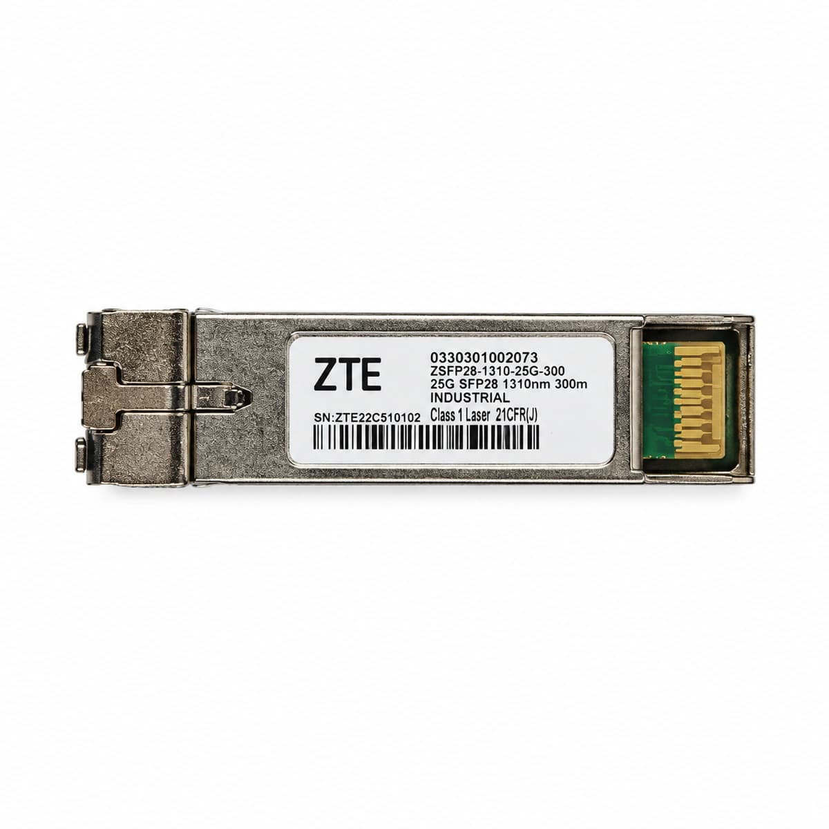
The ZTE 25G SFP28 1310nm 300m Industrial (SM-300M-1310-25G-I) is a hardened 25.78Gbps optical transceiver engineered for 5G wireless fronthaul up to 300 meters over single-mode fiber with industrial -40°C to +85°C operating tolerance.

Equipment information

Brand
ZTE
Equipment model
ZTE 25G SFP28 300m Industrial
Equipment type
Optical communications and networking
Controller / software version
Confirm against the installed equipment
View full product specifications
ZTE 25G SFP28 300m Industrial Official Product View 4

Information below comes from the current product catalogue. Confirm the controller, software version and configuration of the installed equipment separately.

Physical Form Factor
SFP28 (dedicated to 5G fronthaul)
Data Rate
25.78 Gbps
Central Wavelength
1310 nm
Maximum Distance
0.3 km
Fiber Type
Single-Mode Fiber (SMF) (SMF)
Optical Connector
Duplex LC Connector

Alarms & troubleshooting

RX_LOS (Receiver Loss of Signal)
Port LED solid red, Link LED off
Multimode patch cord broken or excessive bend radius, severe LC connector contamination, or remote 25G SFP28 transmitter disabled/failed.
1. Check DDM real-time Rx optical power to verify if it is below the -10.3 dBm sensitivity threshold. 2. Inspect and clean LC multimode connector end-faces with a fiber scope, or replace with a verified OM3/OM4 patch cord. 3. Log into remote device and run 'display transceiver interface' to check Tx power and laser emission status. 4. If optical line and remote Tx are normal, replace the local ZTE 25G industrial transceiver.
TX_FAULT (Transmitter Fault / Laser Bias Alarm)
Port LED flashing amber (2Hz), no optical output
Aging 850nm VCSEL laser component, internal driver IC breakdown, or laser bias current exceeding maximum high threshold.
1. Run 'show transceiver detail' to verify if Tx Bias Current is out of range (normal range: 2 to 12 mA). 2. Administratively cycle the port with 'shutdown' then 'undo shutdown' to reset the transceiver internal register. 3. Reseat the module and inspect gold fingers for mechanical scratching, debris, or oxidation. 4. If Tx Fault condition persists and laser remains dark, replace the SFP28 module and collect diagnostic logs.
MODULE_OVERTEMP (Transceiver High Temperature Alarm)
Chassis ALM LED solid amber, port alarm signaled
Outdoor cabinet ventilation blocked, chassis fan tray failure causing ambient temp to exceed industrial limit (>+85°C), or poor thermal contact inside slot.
1. Query DDM telemetry to verify if internal temperature has breached the +85°C threshold. 2. Inspect chassis fan speeds and intake dust filters, clean accumulated dust to restore airflow. 3. Check outdoor cabinet heat exchanger or TEC cooling unit to bring ambient temperature into spec. 4. If rack cooling is normal and only one module overheats, reseat it to improve cage thermal contact; replace module if condition persists.
FEC_DEG_ALM (Post-FEC Uncorrectable Degrade Alarm)
Port LED blinking amber slowly (1Hz), throughput degraded
Excessive modal dispersion exceeding distance budget, contaminated LC facet, causing optical eye closure and uncorrectable RS-FEC (IEEE 802.3by) code words.
1. Run 'display interface' to confirm whether error counters indicate accumulating Uncorrected FEC Words and packet drops. 2. Verify fiber link distance: max 70m over OM3, max 300m over OM4; ensure the physical run is within budget. 3. Clean both optical patch cord end-faces and transceiver optical sub-assemblies using specialized cleaning cassettes. 4. Check if Rx power is near receiver overload (>+2.4 dBm) or sensitivity threshold; adjust attenuation or re-cable accordingly.
FEC_MODE_MISMATCH (FEC Configuration Mismatch / Link Down)
Optical emission normal, port Link LED completely off
Inconsistent Forward Error Correction mode configuration between endpoints on 25GBASE-R interfaces (e.g., Base-R FEC/CL74 vs. RS-FEC/CL108 vs. disabled).
1. Log into the local switch/router and run 'display port interface' to inspect current FEC operational mode. 2. Per IEEE 802.3by 25G standard, manually configure both link endpoints to matching 'port fec rs' (Clause 108). 3. Check auto-negotiation settings and lock both ends to forced 25G speed ('speed 25000'). 4. Save configurations, verify the physical layer transitions from DOWN to UP, and test end-to-end connectivity.

Access Complete Maintenance & Full Alarm Troubleshooting Manual

This page lists high-frequency critical alarm codes commonly encountered in field maintenance. Comprehensive manufacturer troubleshooting matrices, board-level repair guides, detailed electrical schematics, and firmware commissioning manuals are delivered alongside equipment upon formal project procurement, accompanied by dedicated FAE technical support.

Share on-site information

  1. 01

    Identify the exact model

    Record the nameplate, system model and controller or module model.

  2. 02

    Keep the alarm details

    Record the full alarm text, indicator colour, timing and whether it persists.

  3. 03

    Describe recent changes

    Note recent replacements, software updates or configuration changes.

Record information visible in the existing interface. Electrical measurements, disassembly and replacement should follow the applicable manufacturer's manual and be performed by qualified personnel.

Your model and these details will be added to the enquiry form for you to review before sending.

Related technical articles

Browse the technical guides or send a question about this model.

View all articles

Need a replacement module or supporting equipment?

Confirm the full model, system configuration and compatibility requirements before enquiring about suitable products.

Ask about suitable products

Have a model and an on-site issue?

Share the exact model, alarm text and observed symptoms to help identify relevant information and compatibility requirements.

Request technical support