ZTE / Power management

PSU-AC Equipment information & support

The ZTE PSU-AC is a high-efficiency telecom-grade AC/DC switch-mode rectifier module that converts 85VAC-300VAC input to a regulated -48VDC output for telecom base stations and transmission sites.

Equipment information

Brand
ZTE
Equipment model
PSU-AC
Equipment type
Power management
Controller / software version
Confirm against the installed equipment
View full product specifications
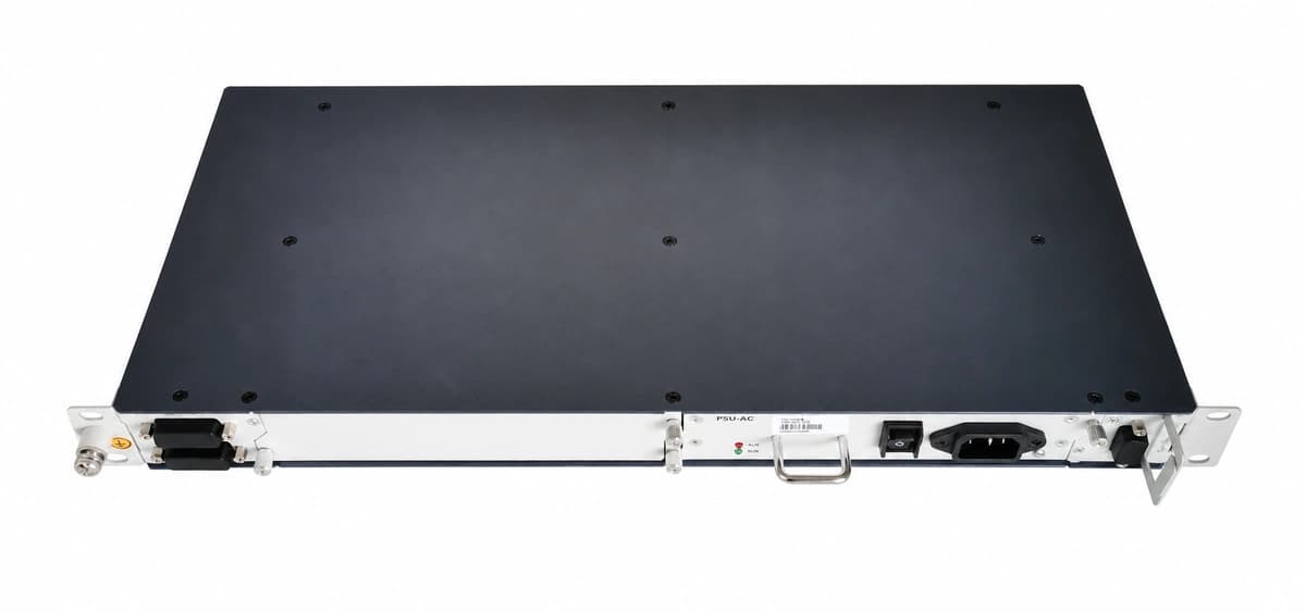
ZTE PSU-AC Official White Background Photo View 4

Information below comes from the current product catalogue. Confirm the controller, software version and configuration of the installed equipment separately.

AC Input Voltage Range
80VAC ~ 300VAC (Nominal 220VAC) VAC
Smart Monitoring Controller
Built-in CAN Bus & Autonomous Current Sharing
Cooling Method
Built-in temperature-controlled brushless DC fan
Nominal Output Voltage
-48VDC (-42VDC ~ -58VDC Continuously Adjustable) VDC
Rated Output Current
30A (Output Power 1740W)
Managed Rectifier Capacity
Compact Hot-Swappable Module (Fits ZTE Subracks)

Alarms & troubleshooting

AC_FAIL
Power LED OFF, Alarm Red LED solid ON
Grid blackout, AC input circuit breaker tripped, or AC voltage below 85VAC undervoltage cutoff point.
1) Measure phase-to-neutral voltage at the AC input terminals using a calibrated DMM. 2) Inspect upstream AC distribution breakers and surge protective devices (SPD). 3) Ensure input socket seating is tight and free of pitting. 4) If voltage is verified within 85-300VAC and the alarm persists, swap the PSU-AC module.
DC_OVER_VOLT
Alarm Red LED solid ON, module locked out without output
Internal PWM loop regulation failure or feedback optocoupler fault driving output voltage above the high-voltage shutdown (HVSD) limit (-58.5VDC to -60VDC).
1) Unseat the module to completely discharge internal DC bus capacitors, reinsert after 30 seconds to test for transient logic lockout. 2) Measure common DC busbar voltage with a multimeter to rule out CSU monitor sensing drift. 3) If the module latches off again with overvoltage upon reinsertion, replace the damaged unit.
COMM_FAIL
Yellow Alarm LED flashing
CAN or RS485 communication bus lost between the rectifier module and the Central Supervisory Unit (CSU), or communication address collision.
1) Verify the module is fully seated into the subrack slot so the backplane communication pins mate properly. 2) Inspect RJ45/terminal blocks and verify the 120-ohm CAN bus terminating resistor is installed. 3) Check controller menus to resolve slot assignment or module ID address collisions. 4) Clean contact fingers with electrical cleaner and reseat.
LLVD_ACT
Controller Alarm Red LED solid ON, LLVD trip indicator illuminated
Prolonged AC utility outage caused battery depletion down to the preset Load Low Voltage Disconnect threshold (e.g. -45.0VDC), causing the contactor to drop non-critical branch loads.
1) Deploy and start a mobile emergency diesel generator to restore AC feeding immediately. 2) Verify that primary transmission and core network equipment remain energized via the priority bus. 3) Once AC input is restored, confirm that rectifiers restart automatically, re-engage the LLVD contactor, and initiate controlled current-limited battery recharge.
FAN_FAIL
Yellow Alarm LED solid ON, module operates in derated output mode
Cooling fan locked rotor, foreign object blockage, tachometer feedback wire fault, or excessive dust accumulation causing heat dissipation failure and over-temperature derating.
1) Inspect the front air intake grill and remove accumulated dust, lint, or physical obstructions. 2) Power down and manually spin fan blades with an insulated tool to verify free mechanical rotation. 3) If the rotor is mechanically seized or damaged, replace the fan assembly with an approved OEM spare. 4) If the fault persists after clearing obstructions, replace the PSU-AC module.

Access Complete Maintenance & Full Alarm Troubleshooting Manual

This page lists high-frequency critical alarm codes commonly encountered in field maintenance. Comprehensive manufacturer troubleshooting matrices, board-level repair guides, detailed electrical schematics, and firmware commissioning manuals are delivered alongside equipment upon formal project procurement, accompanied by dedicated FAE technical support.

Share on-site information

  1. 01

    Identify the exact model

    Record the nameplate, system model and controller or module model.

  2. 02

    Keep the alarm details

    Record the full alarm text, indicator colour, timing and whether it persists.

  3. 03

    Describe recent changes

    Note recent replacements, software updates or configuration changes.

Record information visible in the existing interface. Electrical measurements, disassembly and replacement should follow the applicable manufacturer's manual and be performed by qualified personnel.

Your model and these details will be added to the enquiry form for you to review before sending.

Related technical articles

Browse the technical guides or send a question about this model.

View all articles

Need a replacement module or supporting equipment?

Confirm the full model, system configuration and compatibility requirements before enquiring about suitable products.

Ask about suitable products

Have a model and an on-site issue?

Share the exact model, alarm text and observed symptoms to help identify relevant information and compatibility requirements.

Request technical support