Vertiv / Site energy systems

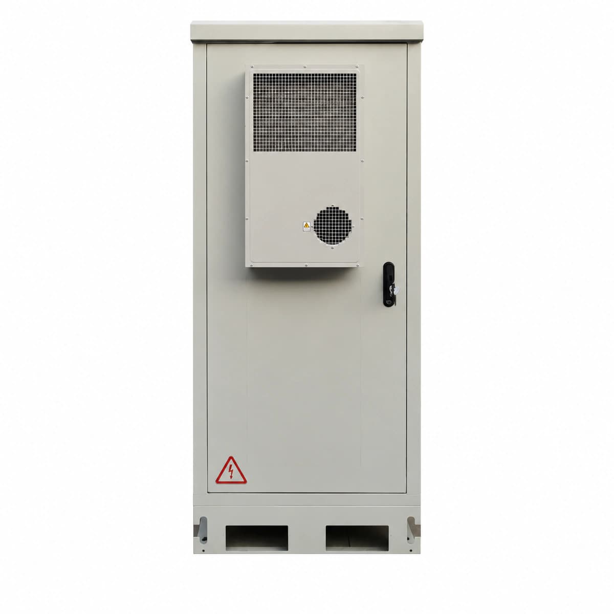
Vertiv 2.1m Outdoor Telecom Power Cabinet (NetSure) Equipment information & support

The Vertiv 2.1m Outdoor Telecom Power Cabinet is a carrier-grade, all-weather integrated infrastructure unit designed for remote macro base stations and harsh industrial sites. Incorporating the NetSure 731 subrack with R48-2900U rectifiers, it delivers up to 300A continuous -48V DC power with heavy-duty thermal insulation.

Equipment information

Brand
Vertiv
Equipment model
Vertiv 2.1m Outdoor Telecom Power Cabinet (NetSure)
Equipment type
Site energy systems
Controller / software version
Confirm against the installed equipment
View full product specifications
Vertiv 2.1m Outdoor Telecom Power Cabinet (NetSure 731 / R48-2900U Rectifiers 300A -48V DC IP55)

Information below comes from the current product catalogue. Confirm the controller, software version and configuration of the installed equipment separately.

Cabinet Physical Height
2.1m Carrier-Grade Heavy-Duty Outdoor Integrated Power Cabinet
Built-in Power Subsystem
Integrated NetSure 731 Subrack with R48-2900U High-Reliability Rectifiers
Total DC Distribution Capacity
300A High-Capacity DC Busbars with Dual-Stage LLVD/BLVD Disconnect
Thermal Management Architecture
Double-Wall Insulated Doors + Door-Mounted Industrial Heat Exchanger
Protection Rating
IP55 Anti-Corrosion Powder Coating Resistant to UV, Acid Rain & Salt Spray
Internal Battery Storage Space
Dedicated Battery Compartment for Multi-String Gel or LiFePO4 Batteries

Alarms & troubleshooting

AC_FAIL (AC Mains Failure / Phase Loss)
Controller Alarm LED solid red; Rectifier green Power LED off, yellow Protection LED flashing
Utility grid outage, AC input molded case circuit breaker (MCCB) trip, input fuse blown, or phase voltage unbalance exceeding 30%
1. Measure L1/L2/L3 to N voltages at the AC input terminal block using a multimeter (normal range: 85V~300VAC). 2. Verify that the AC main circuit breaker and SPD upstream branch breaker are closed. 3. Inspect terminal lugs for loose connections, carbonization, or oxidation; torque to factory specification. 4. If AC voltages are nominal and balanced but the alarm persists, reboot the NCU/controller and verify AC voltage sensing calibration.
DC_LOW_DISC (DC Bus Undervoltage / LLVD Trip)
Controller Critical LED solid red with continuous audible buzzer; LLVD contactor status LED off
Extended AC power outage exhausting battery backup to threshold (43.2V~45.0VDC), total rectifier module failure, or major DC short/overload
1. Deploy an emergency mobile diesel generator to the cabinet input transfer switch to restore AC power immediately. 2. If AC power is present but rectifiers are offline, verify individual rectifier circuit breakers and clear HVSD lockouts. 3. Before manual override of the LLVD contactor via NCU, verify absence of short circuits across the DC busbars. 4. Once charging commences, confirm DC bus voltage recovers above 48.0VDC and LLVD automatically re-engages non-critical loads.
RECT_TEMP_SHUT (Rectifier Over-Temperature Shutdown)
Faulty rectifier yellow Protection LED solid on, green Power LED off; NCU logs Major alarm
Internal rectifier cooling fan failure, severe air filter clogging, or outdoor cabinet thermal management (air conditioner/heat exchanger) failure raising ambient temp above 65°C
1. Inspect the rectifier front panel intake grille and external filter mesh; vacuum dust accumulation. 2. Hot-swap out the affected module; inspect blind-mate backplane connectors for damage and verify the internal fan spins freely. 3. Check outdoor cabinet door cooling/heat exchanger circuit breaker and thermostat to confirm thermal management is active. 4. Reinsert the module; if fan tachometer fault and over-temp lock persist after cool down, replace the rectifier module (e.g., R48-3000e3).
SPD_FAIL (AC Surge Protective Device Failure)
SPD inspection window turns from green to red; Controller panel yellow Warning LED on
Lightning surge strike or prolonged grid transient degradation tripping MOV thermal disconnect; or loose signal wiring on the SPD remote auxiliary contact
1. Visually check the SPD modular cartidges; identify which phase indicator has flagged red (L1/L2/L3 or N-PE). 2. Verify the SPD dedicated upstream breaker is operational; inspect the ground cable bond to the master ground bar (< 10 ohms). 3. Open the SPD upstream disconnect, pull out the defective cartridge, and plug in an identical rated replacement (e.g., Class II, In 20kA, Imax 40kA). 4. Close the circuit breaker; confirm on the NCU LCD that the SPD fault alarm clears automatically.
CAB_FAN_FAIL (Cabinet Heat Exchanger Fan Failure)
Door climate interface Alarm LED flashing red; Controller logs Major alarm
Internal/external loop centrifugal fan bearing lock, tachometer Hall signal loss, DC 48V power fuse blown, or driver board malfunction on the door heat exchanger
1. Open the cabinet outer door, isolate heat exchanger power, and manually spin the blower wheels to check for mechanical binding or debris obstruction. 2. Measure DC voltage at the heat exchanger power terminals to verify 48VDC is present and internal branch fuses are intact. 3. Verify that the PWM speed regulation and tachometer feedback wiring harness is seated securely into the climate controller header. 4. If DC voltage is present but the blower fails to rotate or generate speed pulses, replace the defective 48VDC fan assembly or interface driver board.

Access Complete Maintenance & Full Alarm Troubleshooting Manual

This page lists high-frequency critical alarm codes commonly encountered in field maintenance. Comprehensive manufacturer troubleshooting matrices, board-level repair guides, detailed electrical schematics, and firmware commissioning manuals are delivered alongside equipment upon formal project procurement, accompanied by dedicated FAE technical support.

Share on-site information

  1. 01

    Identify the exact model

    Record the nameplate, system model and controller or module model.

  2. 02

    Keep the alarm details

    Record the full alarm text, indicator colour, timing and whether it persists.

  3. 03

    Describe recent changes

    Note recent replacements, software updates or configuration changes.

Record information visible in the existing interface. Electrical measurements, disassembly and replacement should follow the applicable manufacturer's manual and be performed by qualified personnel.

Your model and these details will be added to the enquiry form for you to review before sending.

Related technical articles

Browse the technical guides or send a question about this model.

View all articles

Need a replacement module or supporting equipment?

Confirm the full model, system configuration and compatibility requirements before enquiring about suitable products.

Ask about suitable products

Have a model and an on-site issue?

Share the exact model, alarm text and observed symptoms to help identify relevant information and compatibility requirements.

Request technical support