Vertiv / DC power systems

R48-4300E3 Equipment information & support

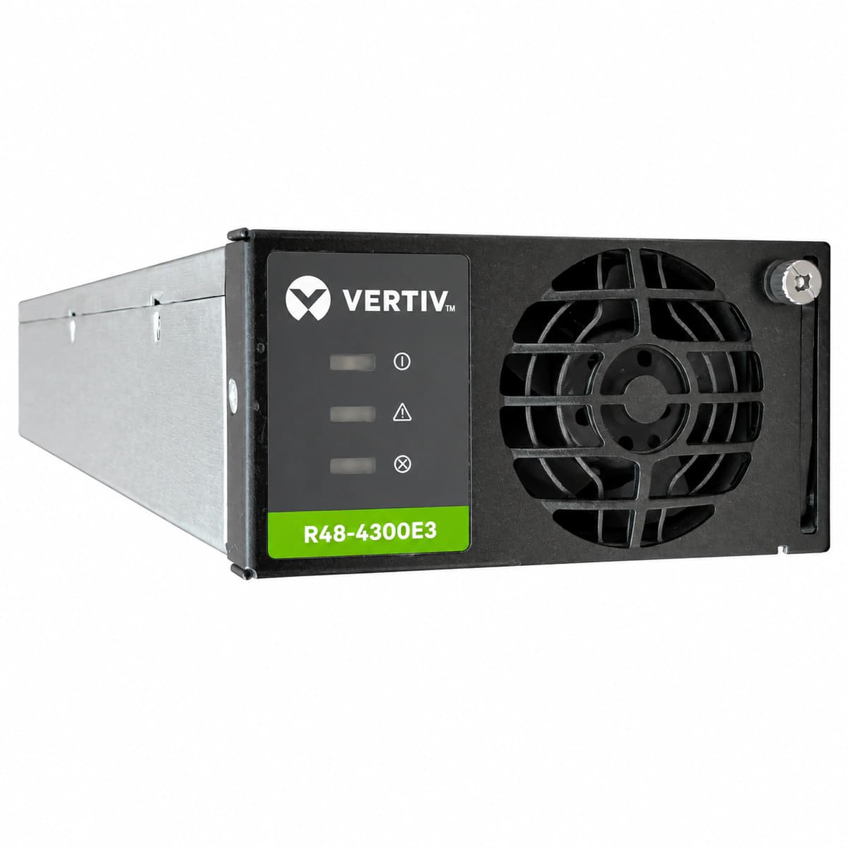
Vertiv R48-4300E3 is an ultra-high power density telecom rectifier module engineered for large communication hubs and data centers, offering -48VDC output up to 4300W with over 96.2% conversion efficiency.

Equipment information

Brand
Vertiv
Equipment model
R48-4300E3
Equipment type
DC power systems
Controller / software version
Confirm against the installed equipment
View full product specifications
Vertiv R48-4300E3 Rectifier Module View 1

Information below comes from the current product catalogue. Confirm the controller, software version and configuration of the installed equipment separately.

Rated Output Power
4300W
Rated Output Current
89.6A
Power Conversion Efficiency
96.2%
AC Input Voltage Range
85V~300V AC
Nominal DC Output Voltage
-48V DC (42V~58V)
Cooling Method
Built-in intelligent variable-speed temperature-controlled fan with forced-air cooling

Alarms & troubleshooting

AC_IN_FAIL (AC Input Abnormal / Mains Fail)
Green LED Off, Yellow LED Solid
AC grid outage, phase loss, input voltage out of operational range (<85 VAC or >305 VAC), or upstream AC input breaker trip.
1. Measure AC input voltage (L-N) at the shelf backplane terminals using a True-RMS DMM. 2. Verify upstream AC branch circuit breaker status; reset if tripped after clearing external faults. 3. If input voltage is verified within 85-300 VAC and terminals are secure, re-seat the rectifier module; replace the module if fault persists.
OUT_OV_HVSD (DC Output Overvoltage Lockout)
Green LED Off, Red LED Solid
Internal PWM loop regulation failure or secondary feedback circuit breakdown, causing DC output to exceed hardware threshold (typically 59.5V ± 0.5V DC) and triggering latching HVSD.
1. Pull the rectifier module partially out of the shelf slot to isolate it from AC/DC backplane. 2. Wait 30 seconds for internal bulk bus capacitors to fully discharge, then push the module back into place. 3. If the module trips back into Red LED latching overvoltage protection immediately upon restart, internal circuitry is defective; replace the module.
OTP_SHUTDOWN (Over-Temperature Protection / Shutdown)
Green LED Blink/Off, Yellow LED Solid (Derating) or Red LED Solid (Shutdown)
Ambient temperature exceeds operating limits (>75°C), front air inlet mesh is clogged, rear exhaust is obstructed, or internal heatsink thermistor detected critical thermal threshold.
1. Inspect site air conditioning / HVAC systems to lower rack inlet ambient temperature below 45°C. 2. Clear dust from the front grille and ensure at least 100mm clearance behind the exhaust vent for laminar airflow. 3. Allow the module to cool; it will automatically recover once temperature falls below clearance limit. If alarm persists at 25°C ambient, replace the rectifier.
FAN_FAULT (Fan Locked Rotor / Tacho Failure)
Red LED Solid or Flashing (0.5Hz)
Fan rotor mechanically blocked by foreign objects, heavy dust clogging the bearing, open circuit in tachometer wire, or defective PWM drive circuit.
1. De-energize and unseat the rectifier module; visually inspect the front fan intake for debris or blockage. 2. Clean dust using compressed air and check that the fan blades spin freely by manual rotation. 3. Re-insert the module into the subrack; if the fan fails to spin at self-test or tacho alarm remains active, replace the fan assembly or rectifier unit.
CAN_COMM_FAIL (CAN-bus Communication Failure & Current Share Fault)
Green LED Solid, Yellow LED Flashing (0.5Hz)
Poor contact on rear backplane blind-mate connector, system supervisory controller (M830B/NCU) failure, CAN bus termination resistor mismatch, or autonomous mode fallback causing >10% load share imbalance.
1. Check the system controller (e.g., M830B/NCU) GUI/LCD to verify if the module is offline or has an address conflict. 2. Firmly reseat the rectifier module into the subrack to ensure full insertion of backplane CAN signal pins. 3. Measure CAN bus termination resistance (nominally 60Ω across CAN_H and CAN_L with system powered off); replace the module if communication cannot be established.

Access Complete Maintenance & Full Alarm Troubleshooting Manual

This page lists high-frequency critical alarm codes commonly encountered in field maintenance. Comprehensive manufacturer troubleshooting matrices, board-level repair guides, detailed electrical schematics, and firmware commissioning manuals are delivered alongside equipment upon formal project procurement, accompanied by dedicated FAE technical support.

Share on-site information

  1. 01

    Identify the exact model

    Record the nameplate, system model and controller or module model.

  2. 02

    Keep the alarm details

    Record the full alarm text, indicator colour, timing and whether it persists.

  3. 03

    Describe recent changes

    Note recent replacements, software updates or configuration changes.

Record information visible in the existing interface. Electrical measurements, disassembly and replacement should follow the applicable manufacturer's manual and be performed by qualified personnel.

Your model and these details will be added to the enquiry form for you to review before sending.

Related technical articles

Browse the technical guides or send a question about this model.

View all articles

Need a replacement module or supporting equipment?

Confirm the full model, system configuration and compatibility requirements before enquiring about suitable products.

Ask about suitable products

Have a model and an on-site issue?

Share the exact model, alarm text and observed symptoms to help identify relevant information and compatibility requirements.

Request technical support