Vertiv / DC power systems

R48-3200e Equipment information & support

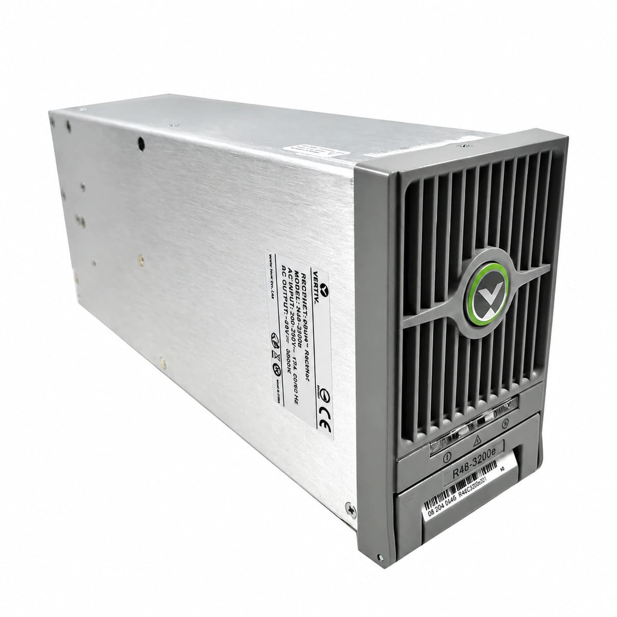
The Vertiv R48-3200e is a high-power-density digital telecom rectifier converting single-phase AC to high-precision -48V DC, engineered for extreme reliability in enterprise data hubs and 5G network centers.

Equipment information

Brand
Vertiv
Equipment model
R48-3200e
Equipment type
DC power systems
Controller / software version
Confirm against the installed equipment
View full product specifications
R48-3200e Official Product View 2

Information below comes from the current product catalogue. Confirm the controller, software version and configuration of the installed equipment separately.

Nominal DC Output Voltage
-48 V DC
AC Input Voltage Range
85 ~ 300 V AC
Physical Dimensions Spec
132 × 85 × 287 mm
Operating Temperature
-40 ~ +75 °C

Alarms & troubleshooting

DC_OVP_LOCK (DC Output Overvoltage Lockout)
Power LED (Green) OFF, Fault LED (Red) Solid ON
Internal feedback loop malfunction or external surge causing DC bus voltage to exceed hardware threshold (>59.5V), triggering HVSD lockout
1. Unseat the rectifier from the shelf and wait 3 minutes for bus capacitors to discharge; 2. Verify system controller overvoltage settings match module specifications; 3. Re-seat module and monitor DC bus; replace rectifier if lockout reoccurs immediately.
AC_IN_FAIL (AC Mains Input Abnormal/Fail)
Power LED (Green) OFF, Protection LED (Yellow) Solid ON, Fault LED (Red) OFF
Mains grid outage, tripped input AC breaker, or line voltage outside operating limits (85VAC to 300VAC)
1. Measure AC voltage at the shelf backplane input terminals (nominal 85VAC–300VAC); 2. Check and reset corresponding AC feed circuit breaker on the ACDU panel; 3. Inspect module rear connector pins for thermal damage, arcing, or physical displacement.
OVER_TEMP (Module Thermal Derating / Shutdown)
Derating: Green and Yellow LEDs Solid ON; Thermal Shutdown: Green OFF, Yellow LED Solid ON
Ambient temperature exceeding +65°C, HVAC cooling failure, blocked front/rear air vents, or severe internal dust buildup
1. Inspect site HVAC system and verify ambient intake temperature is within -40°C to +75°C; 2. Clear dust and obstructions from front intake grilles and rear exhaust areas; 3. Clean internal heatsinks using low-pressure dry air; replace module if temperature sensor is defective.
FAN_FAIL (Cooling Fan Locked Rotor / Failure)
Power LED (Green) Flashing, Fault LED (Red) Solid ON
Mechanical obstruction in fan blades, failure of the internal fan driver circuit, or loss of tachometer feedback
1. Visually check fan intake for foreign objects; with power off, verify the fan spins freely by hand; 2. Reseat the module and verify if the fan spins at full speed during initial POST sequence; 3. If the fan remains stationary or alarm persists, replace the fan assembly or swap the rectifier.
CAN_COMM_FAIL (CAN-bus Communication Loss & Current Sharing Fault)
Power LED (Green) Solid ON, Protection LED (Yellow) Slow Flashing (0.5Hz)
CAN-H/CAN-L differential line open-circuit between module and supervisory controller (e.g., M530S/M830B), dirty gold finger pins, or missing 120Ω bus terminator
1. Access controller web/local GUI and check whether the rectifier ID is missing or in conflict; 2. Unseat rectifier, clean the backplane communication pins with contact cleaner, and firmly reseat; 3. Measure CAN bus resistance between CAN-H and CAN-L across shelf (should measure ~60Ω with both 120Ω terminators active).

Access Complete Maintenance & Full Alarm Troubleshooting Manual

This page lists high-frequency critical alarm codes commonly encountered in field maintenance. Comprehensive manufacturer troubleshooting matrices, board-level repair guides, detailed electrical schematics, and firmware commissioning manuals are delivered alongside equipment upon formal project procurement, accompanied by dedicated FAE technical support.

Share on-site information

  1. 01

    Identify the exact model

    Record the nameplate, system model and controller or module model.

  2. 02

    Keep the alarm details

    Record the full alarm text, indicator colour, timing and whether it persists.

  3. 03

    Describe recent changes

    Note recent replacements, software updates or configuration changes.

Record information visible in the existing interface. Electrical measurements, disassembly and replacement should follow the applicable manufacturer's manual and be performed by qualified personnel.

Your model and these details will be added to the enquiry form for you to review before sending.

Related technical articles

Browse the technical guides or send a question about this model.

View all articles

Need a replacement module or supporting equipment?

Confirm the full model, system configuration and compatibility requirements before enquiring about suitable products.

Ask about suitable products

Have a model and an on-site issue?

Share the exact model, alarm text and observed symptoms to help identify relevant information and compatibility requirements.

Request technical support