Vertiv / DC power systems

R48-3000e3 Equipment information & support

The Vertiv R48-3000e3 is an industrial high-efficiency switch-mode telecommunication rectifier module designed to convert standard AC input into regulated -48V DC power with up to 3000W output for telecom and enterprise mission-critical DC systems.

Equipment information

Brand
Vertiv
Equipment model
R48-3000e3
Equipment type
DC power systems
Controller / software version
Confirm against the installed equipment
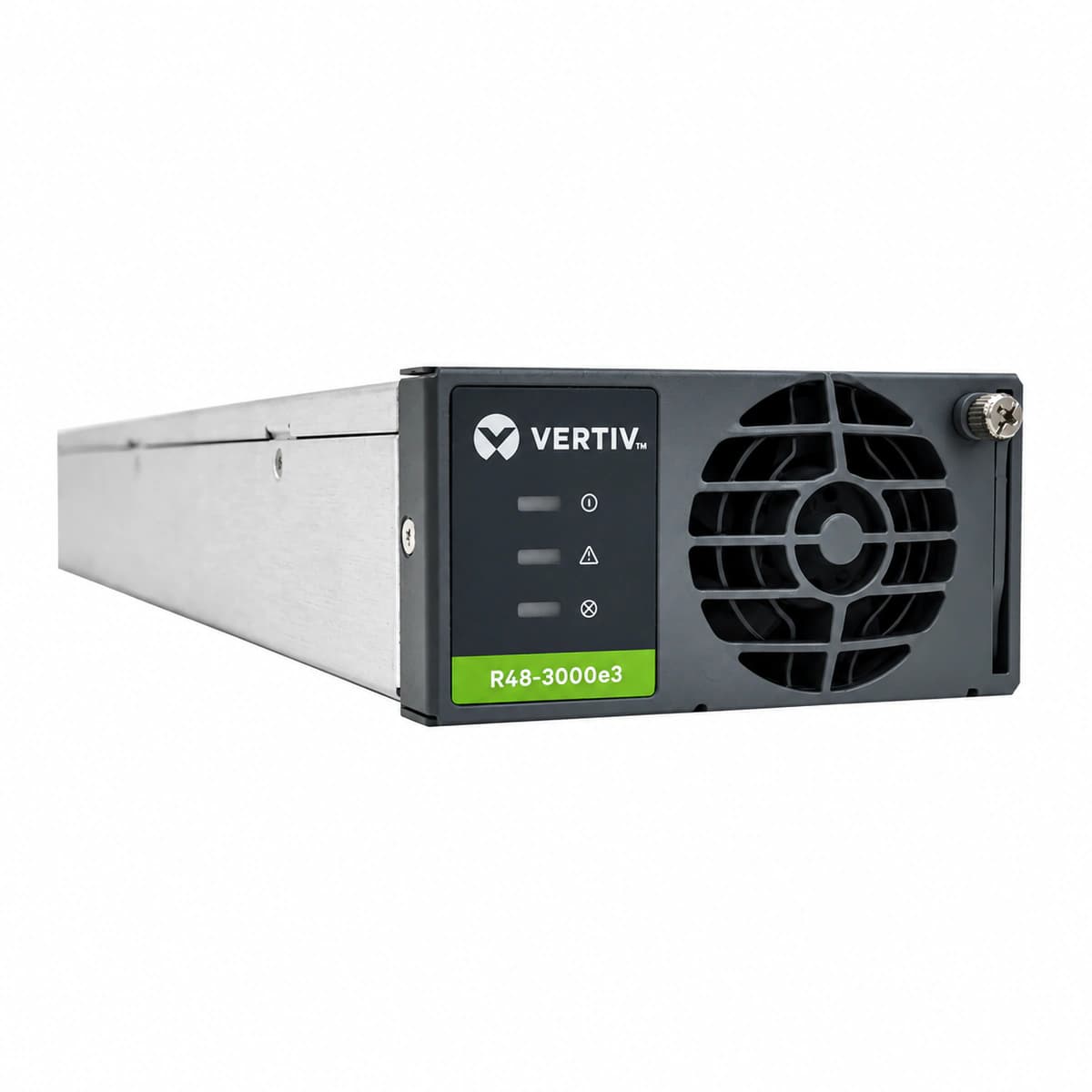
View full product specifications
R48-3000e3 Official Product View 1

Information below comes from the current product catalogue. Confirm the controller, software version and configuration of the installed equipment separately.

Output Voltage Range
-42 ~ -58 VDC
AC Input Voltage Range
85 ~ 300 VAC
Output Power Factor PF
≥ 0.99
Operating Temperature
-40 ~ +75 °C
Total Harmonic Distortion (THD)
≤ 5 %
Cooling Method
Forced-air cooling with intelligent speed control of the built-in fan

Alarms & troubleshooting

AC_IN_FAIL (AC Input Abnormal / Failure)
Green (Power) LED OFF, Yellow (Protection) LED Solid ON (All LEDs OFF if total blackout)
AC grid outage; input voltage below 85VAC or above 305VAC protection limit; AC input breaker tripped or upstream fuse blown.
1. Measure AC input terminal voltage at the slot backplane using a DMM to confirm it is within 85VAC-305VAC. 2. Verify the branch AC breaker in the ACDU feeding the rectifier module; inspect for short circuit and reset if tripped. 3. Reseat the rectifier firmly into the shelf; if input voltage is verified normal but the fault persists, replace the module.
OUT_HVSD (DC Output Overvoltage Shutdown / Lockout)
Red (Alarm) LED Solid ON, Green (Power) LED OFF
Internal PWM loop failure causing output voltage to exceed hardware threshold (typically >59.5VDC); misconfigured overvoltage limit on the supervisory controller (NCU/M830B) or corrupted bus reference.
1. Disconnect the module from the slot, wait 30 seconds to discharge residual bus capacitance, and reinsert to reset the hardware latch. 2. Access the system controller interface; verify float/boost voltage setpoints and ensure OVP thresholds are correctly configured (nominal float 53.5VDC, OVP 58.5-59.5VDC). 3. If the module triggers red HVSD latch immediately upon re-insertion, internal power components or voltage feedback circuits have failed; replace the unit.
MOD_OTP (Rectifier Over-Temperature Derating / Shutdown)
Yellow LED Solid ON (Derating mode) or Red LED Solid ON (Thermal shutdown), Green LED Flashing/OFF
Ambient temperature exceeds operating limits (>65°C); severe dust accumulation on front inlet grille or air filters blocking airflow; degraded thermal interface on heatsinks.
1. Inspect site HVAC/cooling systems to ensure inlet air temperature to the subrack is maintained between +25°C and +45°C. 2. Clean the module front air inlet mesh and rear exhaust vents using an ESD-safe brush or dry compressed air. 3. Allow the heatsink to cool below the restart threshold (<55°C); the unit should auto-recover. If over-temperature persists despite clean airflow, replace the module.
FAN_FAIL (Cooling Fan Failure / Locked Rotor)
Red (Alarm) LED Flashing (1Hz) or Solid ON, Yellow (Protection) LED Solid ON
Foreign object physically jamming the brushless DC fan; loss of fan tachometer feedback pulse to the internal DSP; loose internal harness or seized sleeve/ball bearing.
1. Visually inspect the front fan grill to confirm no cable ties, debris, or foreign objects are obstructing the fan blades. 2. Remove the module from the shelf and manually spin the fan blades using an insulated probe to check for bearing friction or physical binding. 3. Re-seat the module. If the fan does not spin up during power-on self-test or still reports speed error, replace the rectifier module.
CAN_COMM_FAIL (CAN Bus Communication Loss / Current Sharing Error)
Yellow (Protection) LED Flashing (0.5Hz), Green (Power) LED Solid ON
Poor contact on module backplane CAN-bus signal pins; system controller (NCU) crash or bus address conflict; missing 120-ohm bus termination resistor causing frame CRC errors; rectifier drops to autonomous fallback mode with current sharing disabled.
1. Verify if the system controller (NCU) is functional and communicating with other rectifiers; perform a controller soft-reboot if communication is frozen globally. 2. Unseat the module and inspect the gold finger/connector pins on both the module and the subrack backplane for bent pins, dust, or corrosion; firmly reseat. 3. Measure termination resistance across CAN_H and CAN_L lines (nominal ~60 ohms when unpowered with both terminators connected). If physical bus is intact but the rectifier fails to register and exhibits severe current unbalance (>±10%), replace the module.

Access Complete Maintenance & Full Alarm Troubleshooting Manual

This page lists high-frequency critical alarm codes commonly encountered in field maintenance. Comprehensive manufacturer troubleshooting matrices, board-level repair guides, detailed electrical schematics, and firmware commissioning manuals are delivered alongside equipment upon formal project procurement, accompanied by dedicated FAE technical support.

Share on-site information

  1. 01

    Identify the exact model

    Record the nameplate, system model and controller or module model.

  2. 02

    Keep the alarm details

    Record the full alarm text, indicator colour, timing and whether it persists.

  3. 03

    Describe recent changes

    Note recent replacements, software updates or configuration changes.

Record information visible in the existing interface. Electrical measurements, disassembly and replacement should follow the applicable manufacturer's manual and be performed by qualified personnel.

Your model and these details will be added to the enquiry form for you to review before sending.

Related technical articles

Browse the technical guides or send a question about this model.

View all articles

Need a replacement module or supporting equipment?

Confirm the full model, system configuration and compatibility requirements before enquiring about suitable products.

Ask about suitable products

Have a model and an on-site issue?

Share the exact model, alarm text and observed symptoms to help identify relevant information and compatibility requirements.

Request technical support