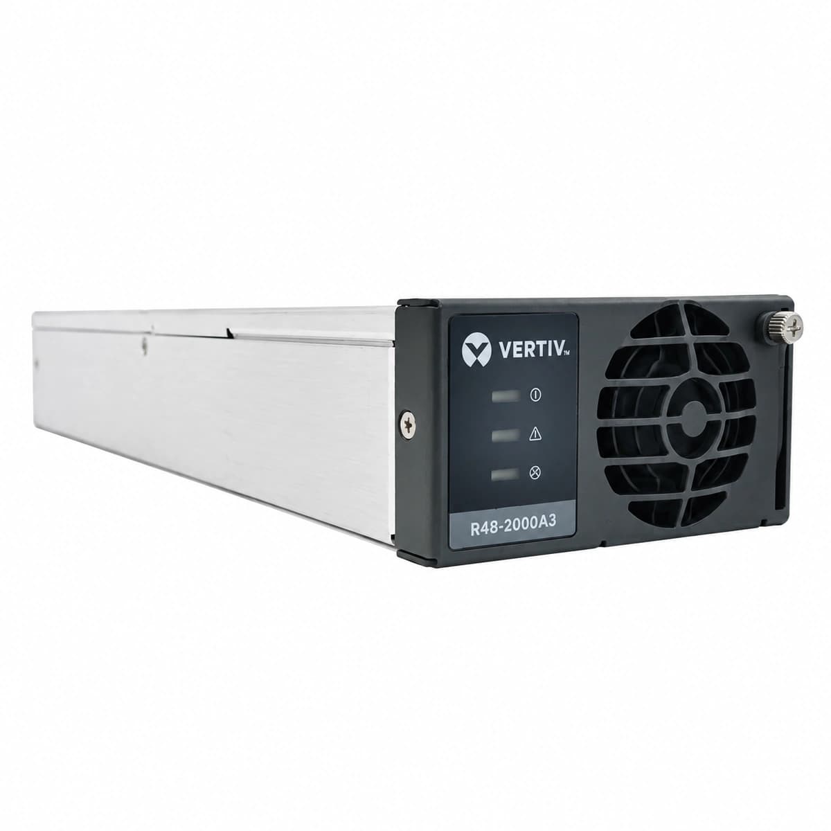
Vertiv R48-2000A3 is a high-reliability 2000W switch-mode telecom rectifier delivering -48VDC/40A with 85VAC~290VAC wide input range and hot-plug capability.
Information below comes from the current product catalogue. Confirm the controller, software version and configuration of the installed equipment separately.
AC Input Voltage Range
85VAC ~ 290VAC (Nominal 220VAC) VAC
Nominal DC Output Voltage
-48 V DC
Cooling Method
Forced-air cooling with built-in temperature-controlled DC fan
Green Power LED off, Yellow Protection LED solid (under/overvoltage) or all LEDs off (complete AC loss)
Utility grid outage, loose terminal screws, input voltage below 85VAC undervoltage limit or exceeding 305VAC, upstream AC MCB tripped.
1. Measure AC voltage across L and N terminals on the backplane slot using a DMM to ensure it is between 85VAC and 305VAC.
2. Inspect the upstream module circuit breaker (MCB) in the AC distribution cabinet for trips or loose wiring.
3. Verify the rectifier is fully seated into the shelf slot and tighten the front latch/handle screws.
4. Once grid voltage normalizes, the rectifier will automatically clear the alarm and restart.
Internal secondary voltage sensing loop fault, PWM controller failure, erroneous voltage target set by CSU controller, or external DC bus voltage back-feed exceeding HVSD threshold (59.5V typ.).
1. Unseat the module, wait 3 minutes for internal bus capacitors to discharge, and reinsert it to clear hardware lockout.
2. Verify float/equalize and OVP thresholds configured on the CSU/SMU controller (standard OVP range: 58.5V to 59.5VDC).
3. If the red LED turns solid immediately after re-plugging without DC output, the internal power stage is defective and requires RMA replacement.
4. Check if other active parallel rectifiers have lost current sharing or if hybrid DC sources are back-feeding overvoltage.
Yellow Protection LED solid during thermal derating; Red Alarm LED solid during thermal shutdown
Cabinet/ambient temperature exceeding 65°C, front air inlet filter heavily choked with dust, back-exhaust recirculation, or internal NTC thermal sensor failure.
1. Inspect front intake grilles and dust mesh; vacuum and clear all accumulated dust and debris.
2. Verify the telecom room air conditioning is operational and ambient intake temperature is kept below 45°C.
3. Ensure blanking panels are properly installed in empty shelf slots to eliminate hot air recirculation from the exhaust.
4. Once internal heatsink temperature drops below the recovery threshold, the unit will automatically resume full rated output.
FAN_FAULT (Cooling Fan Locked/Tachometer Failure)
Red Alarm LED flashing (1Hz) or solid, Yellow Protection LED solid
Physical obstruction jamming the front brushless DC fan, seized fan bearings, disconnected tachometer wire, or blown on-board fan driver power supply.
1. Visually check the front fan blades for cables, wires, or packing debris and safely clear the obstruction.
2. Unseat the module and spin the blades by hand to verify smooth mechanical rotation without friction or bearing stiffness.
3. Disassemble the front grille and inspect the 4-pin fan connector on the control PCB for loose contact.
4. If the rotor spins freely and cables are intact but the fan fails to run upon insertion, replace the fan assembly or RMA the rectifier.
CAN_COMM_FAIL (CAN-bus Communication Interruption)
Green Power LED solid, Yellow Protection LED flashing (0.5Hz–1Hz)
Bent or corroded CAN pins on the backplane connector, supervisory controller (CSU/SMU) crashed or offline, missing 120-ohm termination resistor, or damaged CAN transceiver chip.
1. Confirm the central controller (CSU/SMU) is powered up and operational; perform a controller soft-reboot if necessary.
2. Extract the affected rectifier module and inspect the backplane signal pins for bent, pushed-back, or broken gold contacts.
3. Measure termination resistance across CAN_H and CAN_L lines with system powered off (expected reading is approx. 60 ohms with both 120-ohm resistors in parallel).
4. Note: The module defaults to autonomous safe-mode outputting 53.5VDC during CAN loss; swap the rectifier to isolate whether the fault is in the backplane or module transceiver.
Access Complete Maintenance & Full Alarm Troubleshooting Manual
This page lists high-frequency critical alarm codes commonly encountered in field maintenance. Comprehensive manufacturer troubleshooting matrices, board-level repair guides, detailed electrical schematics, and firmware commissioning manuals are delivered alongside equipment upon formal project procurement, accompanied by dedicated FAE technical support.
Record the nameplate, system model and controller or module model.
02
Keep the alarm details
Record the full alarm text, indicator colour, timing and whether it persists.
03
Describe recent changes
Note recent replacements, software updates or configuration changes.
Record information visible in the existing interface. Electrical measurements, disassembly and replacement should follow the applicable manufacturer's manual and be performed by qualified personnel.
Related technical articles
Browse the technical guides or send a question about this model.