Vertiv / DC power systems

NetSure 801 CA7 Equipment information & support

The Vertiv NetSure 801 CA7 is a mission-critical, high-capacity vertical DC power system engineered for central telecommunication offices and hyperscale data centers, delivering continuous 2000A to 4000A (-48V DC) power via high-efficiency switched-mode rectifiers, integrated NCU monitoring, and comprehensive busbar distribution.

Equipment information

Brand
Vertiv
Equipment model
NetSure 801 CA7
Equipment type
DC power systems
Controller / software version
Confirm against the installed equipment
View full product specifications
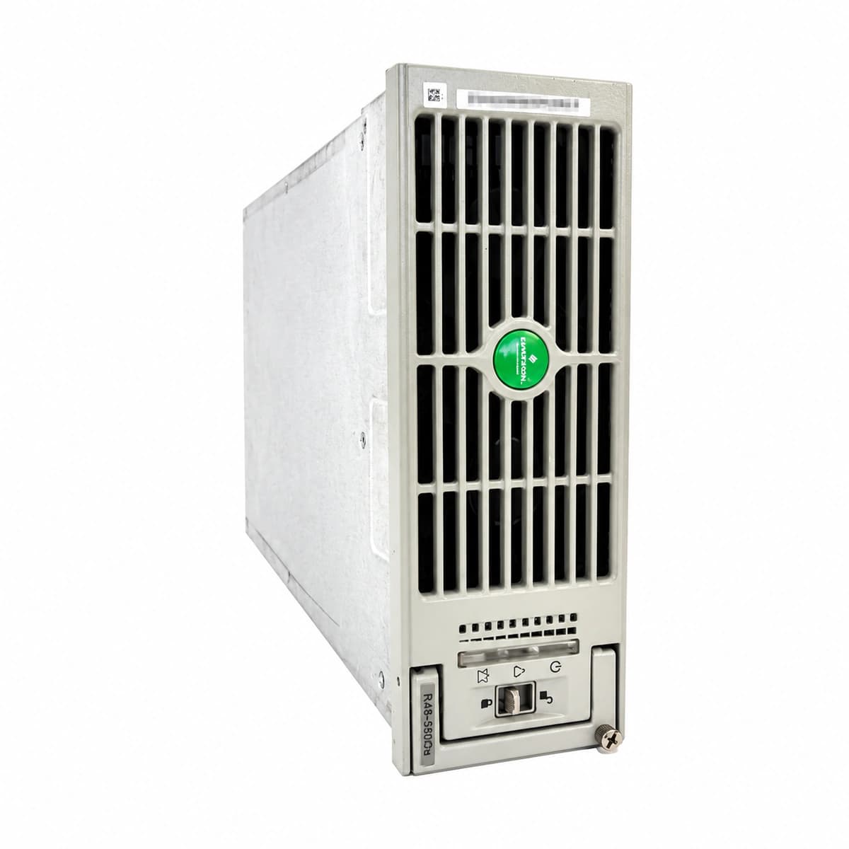
Vertiv NetSure 801 CA7 Large Telecom Power Switching System Cabinet 2000A-4000A -48V DC Official Studio Photo 2

Information below comes from the current product catalogue. Confirm the controller, software version and configuration of the installed equipment separately.

Physical Form Factor
Large Data Center Floor-Standing Combined Cabinet
Rectifier Module Model
Compatible with R48-5800A / R48-4000E Rectifiers
DC Distribution Branches
Multi-Channel NT3/NT4 High-Capacity Fuses & MCCBs
Surge Protection
AC Class C 40kA Lightning Protection
AC Input Voltage Range
304V AC ~ 530V AC (Three-Phase Five-Wire)
System Comprehensive Efficiency
≥ 96.5% (Ultra-High Efficiency)

Alarms & troubleshooting

RECT_HVSD (Rectifier DC Overvoltage Shutdown)
Rectifier module Yellow LED blinking / Red Fault LED solid on; NCU Controller Critical Red LED solid on
Internal rectifier voltage regulation loop failure exceeding HVSD threshold (e.g., -59.5V), or external voltage surge triggering selective hardware shutdown
1. Identify the locked rectifier slot ID via the NCU screen. 2. Remove the faulty module, wait 5 minutes for bus capacitor discharge, and reseat to reset. 3. If HVSD recurs, verify DC bus voltage with a multimeter and replace the failed module.
AC_FAIL (AC Mains Failure / Phase Loss)
Rectifier Green Power LED off, Yellow LED solid on; NCU Controller Major Alarm Red LED solid on with buzzer
Commercial utility blackout, upstream AC distribution breaker trip, tripped AC surge protective device (SPD), or AC input contactor open
1. Measure line-to-line and line-to-neutral voltages at the AC distribution cabinet. 2. Inspect the main AC input breaker and SPD auxiliary contacts. 3. Confirm standby diesel generator (DG) auto-start and automatic transfer switch (ATS) operation.
LLVD_OPEN (Load Low Voltage Disconnect Active)
NCU Controller Critical Red LED flashing, LLVD disconnect indicator illuminated, buzzer sounds continuously
Extended AC outage leading to battery depletion below LLVD setpoint (typically -43.2V to -44.0V), triggering contactor trip to preserve critical loads
1. Confirm actual DC bus voltage; do not manually bypass the LLVD contactor unsafely. 2. Deploy emergency mobile generator to power the AC input. 3. Upon AC recovery, monitor rectifier ramp-up and confirm NCU auto-reconnects LLVD once bus voltage reaches reconnect threshold.
CAN_COMM_FAIL (CAN-Bus Communication Failure)
Affected rectifier module Yellow LED blinking slowly at 0.5Hz; NCU Controller Comm Loss Yellow LED on
Loose CAN communication ribbon/patch cable, oxidized RJ45 connector, missing 120-ohm termination resistor, or damaged module CAN transceiver IC
1. Check CAN communication cables between rectifier subracks and NCU controller ports for secure seating. 2. Verify that the 120-ohm bus termination DIP switch/jumper is enabled on the final subrack. 3. Reseat or swap the affected module to isolate a failed transceiver.
FAN_FAIL (Rectifier Fan Fault)
Faulty rectifier module Yellow LED flashing, output derated; NCU Controller Minor Alarm Yellow LED illuminated
Fan rotor blocked by foreign objects, heavy dust clogging bearings, tachometer speed feedback signal loss, or loose internal fan connector
1. Extract the affected rectifier module and inspect front air intake and rear vents for blockage. 2. Clean dust using compressed air and manually rotate fan blades to check for mechanical seizure. 3. Reinsert module; if the fan alarm persists after self-test, replace the fan assembly or the module.

Access Complete Maintenance & Full Alarm Troubleshooting Manual

This page lists high-frequency critical alarm codes commonly encountered in field maintenance. Comprehensive manufacturer troubleshooting matrices, board-level repair guides, detailed electrical schematics, and firmware commissioning manuals are delivered alongside equipment upon formal project procurement, accompanied by dedicated FAE technical support.

Share on-site information

  1. 01

    Identify the exact model

    Record the nameplate, system model and controller or module model.

  2. 02

    Keep the alarm details

    Record the full alarm text, indicator colour, timing and whether it persists.

  3. 03

    Describe recent changes

    Note recent replacements, software updates or configuration changes.

Record information visible in the existing interface. Electrical measurements, disassembly and replacement should follow the applicable manufacturer's manual and be performed by qualified personnel.

Your model and these details will be added to the enquiry form for you to review before sending.

Related technical articles

Browse the technical guides or send a question about this model.

View all articles

Need a replacement module or supporting equipment?

Confirm the full model, system configuration and compatibility requirements before enquiring about suitable products.

Ask about suitable products

Have a model and an on-site issue?

Share the exact model, alarm text and observed symptoms to help identify relevant information and compatibility requirements.

Request technical support