Vertiv / Power management

NetSure 731 A91-S2 Equipment information & support

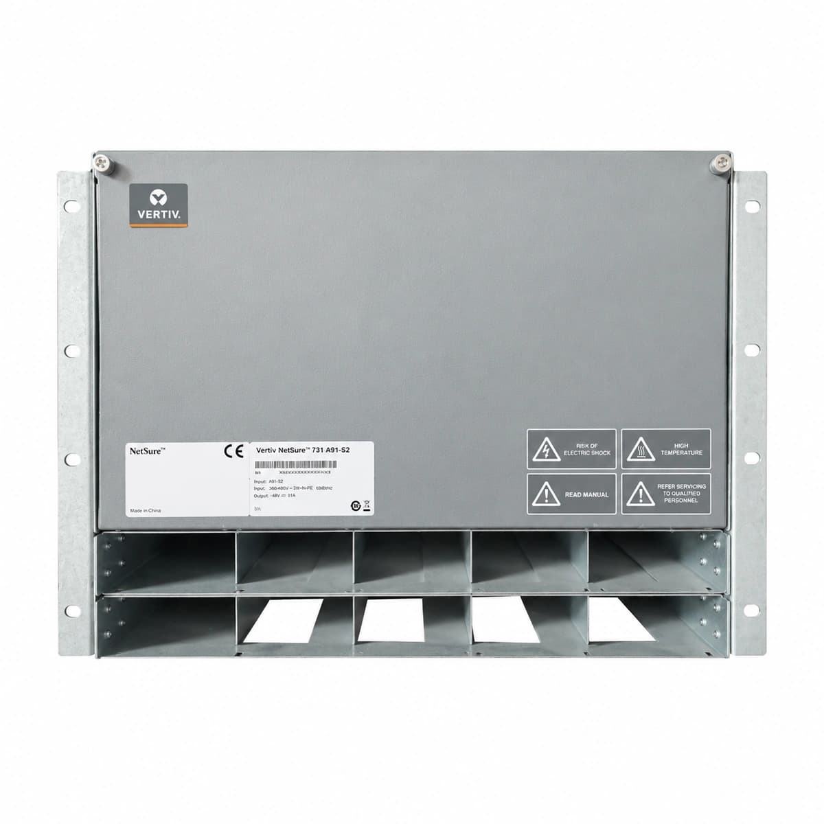
The Vertiv NetSure 731 A91-S2 is a high-density 19-inch 6U embedded telecom DC power system delivering up to 300A output, engineered for 4G/5G wireless sites, central offices, and edge computing nodes.

Equipment information

Brand
Vertiv
Equipment model
NetSure 731 A91-S2
Equipment type
Power management
Controller / software version
Confirm against the installed equipment
View full product specifications
Vertiv NetSure 731 A91-S2 Official White Background Photo View 1

Information below comes from the current product catalogue. Confirm the controller, software version and configuration of the installed equipment separately.

AC Input Voltage Range
85VAC ~ 300VAC (Nominal 220VAC) VAC
Smart Monitoring Controller
M830B / NCU Controller
Cooling Method
Intelligent temperature-controlled cooling
Nominal Output Voltage
-48VDC VDC
Rated Output Current
300A (System Capacity 14.4kW)
Managed Rectifier Capacity
4 Slots for R48-2900U Modules

Alarms & troubleshooting

DC_VOLT_LOW
Red Alarm LED solid on controller, audible buzzer active
Prolonged commercial AC outage depleting batteries; total rectifier cluster shutdown; or massive DC overload dropping bus voltage below 45.0V.
1. Dispatch or start onsite standby diesel generator immediately to restore AC input; 2. Once AC is restored, verify rectifiers auto-restart and current recovers; 3. Inspect DC branches for short-circuit faults and isolate non-essential loads; 4. Monitor battery voltage closely; if dropping toward 43.2V, prepare for imminent BLVD disconnect.
AC_MAINS_FAIL
Yellow Warning LED flashing on controller, battery discharge active
Commercial utility power blackout, upstream AC breaker tripped, phase loss on AC feeders, or input mains dropped below 85VAC cutoff limit.
1. Use a true-RMS multimeter to verify phase-to-phase and phase-to-neutral voltages at the AC terminals; 2. Check upstream distribution panel breakers and surge protection circuit breakers; 3. Consult utility provider for restoration ETA and calculate remaining battery reserve time; 4. Inspect neutral-to-earth bonding and ensure terminal screws are torqued properly.
RECT_COMM_FAIL
Yellow Warning LED on controller, affected rectifier yellow LED flashes slowly
Dislodged CAN communication cable; degraded or oxidized contact pins on rectifier subrack backplane; faulty internal CAN transceiver IC; or module slot ID assignment conflict.
1. Reseat the affected rectifier module firmly into the slot and secure its front locking latch; 2. Inspect the CAN ribbon cable connecting the subrack backplane to the M830B controller; 3. Execute a module re-scan and address auto-learn procedure via M830B menu; 4. Swap the rectifier into a known good slot; if the alarm follows the module, replace the rectifier unit.
RECT_FAULT
Red Fault LED solid on rectifier module, controller logs rectifier hardware alarm
Internal power stage failure (shorted PFC/LLC MOSFETs); output overvoltage latch-off; critical internal over-temperature shutdown; or completely blocked/failed cooling fan.
1. Inspect module air intake and rear exhaust for debris or dust blockages; verify fan spins freely without obstruction; 2. Hot-unplug the module for 3 minutes to allow DC-bus discharge and reset transient overvoltage latches, then reinsert; 3. Verify input AC and bus DC voltages at the backplane; 4. If the red LED illuminates immediately with zero current output upon re-insertion, the module is defective and must be swapped.
BATT_TEMP_PROBE_FAIL
Yellow Warning LED solid on controller, LCD displays temperature probe open/short
Severed or pinched temperature sensor cabling; disconnected terminal block at the M830B analog input interface; or physical drift/failure of the internal NTC/PTC thermistor.
1. Inspect the physical sensor lug affixed to the battery string to ensure it has not detached; 2. Trace cabling along the battery rack to find pinches, tears, or rodent damage; 3. Disconnect probe from controller and measure resistance with a multimeter (standard 10kΩ NTC typically reads ~10kΩ at 25°C); replace if reading infinite ohms; 4. Re-tighten screw terminals on the M830B interface card and test temperature reading on screen.

Access Complete Maintenance & Full Alarm Troubleshooting Manual

This page lists high-frequency critical alarm codes commonly encountered in field maintenance. Comprehensive manufacturer troubleshooting matrices, board-level repair guides, detailed electrical schematics, and firmware commissioning manuals are delivered alongside equipment upon formal project procurement, accompanied by dedicated FAE technical support.

Share on-site information

  1. 01

    Identify the exact model

    Record the nameplate, system model and controller or module model.

  2. 02

    Keep the alarm details

    Record the full alarm text, indicator colour, timing and whether it persists.

  3. 03

    Describe recent changes

    Note recent replacements, software updates or configuration changes.

Record information visible in the existing interface. Electrical measurements, disassembly and replacement should follow the applicable manufacturer's manual and be performed by qualified personnel.

Your model and these details will be added to the enquiry form for you to review before sending.

Related technical articles

Browse the technical guides or send a question about this model.

View all articles

Need a replacement module or supporting equipment?

Confirm the full model, system configuration and compatibility requirements before enquiring about suitable products.

Ask about suitable products

Have a model and an on-site issue?

Share the exact model, alarm text and observed symptoms to help identify relevant information and compatibility requirements.

Request technical support