Vertiv / Power management

NetSure 731 A41-S2 Equipment information & support

The Vertiv NetSure 731 A41-S2 is a 6U 19-inch embedded telecom DC power subrack with a total capacity of up to 300A, housing high-efficiency R48-3000e3 rectifiers and an advanced NCU/M-series controller.

Equipment information

Brand
Vertiv
Equipment model
NetSure 731 A41-S2
Equipment type
Power management
Controller / software version
Confirm against the installed equipment
View full product specifications
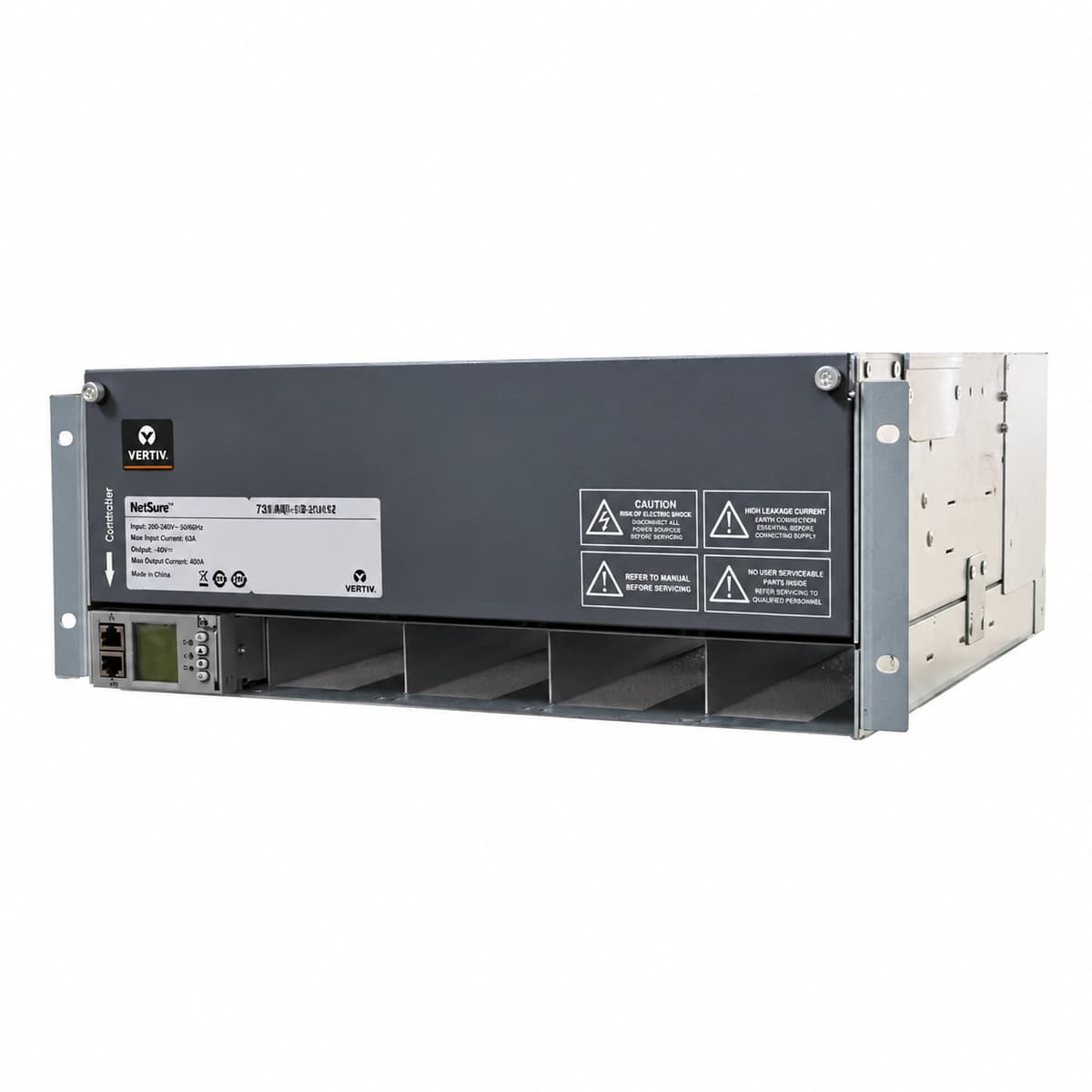
Vertiv NetSure 731 A41-S2 Official White Background Photo View 1

Information below comes from the current product catalogue. Confirm the controller, software version and configuration of the installed equipment separately.

AC Input Voltage Range
85VAC ~ 300VAC (Nominal 220V/380VAC) VAC
Smart Monitoring Controller
M830B / NCU Controller
Cooling Method
Intelligent front-to-rear air cooling
Nominal Output Voltage
-48VDC VDC
Rated Output Current
300A (System Capacity 14.4kW)
Managed Rectifier Capacity
4 Slots for R48-2900U / R48-3200e Modules

Alarms & troubleshooting

AC_MAINS_FAIL
Controller RED LED flashing; Rectifier YELLOW Input LED illuminated
AC input circuit breaker tripped, utility grid outage, or input phase voltage persistently below 80VAC or above 305VAC beyond debounce time.
Measure AC voltage at input terminals across L-N and L-PE using a true-RMS multimeter; inspect upstream distribution panel SPD breakers; reset the input MCB if tripped under normal voltage; dispatch field generator if outage is prolonged.
DC_OVER_VOLT
Controller RED LED constant; faulty Rectifier RED Alarm LED latched and module disabled
Rectifier internal PWM loop failure/feedback optocoupler failure causing uncontrolled output runaway, or erroneous equalize threshold setting exceeding -58.5VDC in controller.
Immediately verify DC bus voltage with an external calibrated meter; identify runaway module address on NCU interface; withdraw the faulted rectifier from the subrack to isolate it; verify controller high voltage shutdown threshold (nominal -58.5V to -59.0V); hot-swap with a spare module.
BLVD_DISCONNECT
Controller RED Alarm LED latched ON; continuous audible buzzer; battery contactor open
Prolonged AC utility outage exhausted battery reserves, driving system voltage down past the BLVD disconnect threshold (-43.2VDC nominal); contactor opened to avoid permanent cell destruction.
Do not mechanically force contactor closed; connect emergency mobile generator to the AC input immediately; when AC recovers, verify rectifiers enter current-limit soft-charge mode (0.1C10 to 0.15C10); confirm automatic contactor re-engagement once bus rises past hysteresis threshold (~-48.0VDC).
RECTIFIER_COMM_FAIL
Controller YELLOW Warning LED solid; missing Rectifier front panel GREEN LED blinking
Interrupted CAN bus communication between rectifier module and NCU controller, bent/corroded backplane connector pins, or damaged internal CAN transceiver circuitry.
Reseat the uncommunicative rectifier by unlocking, extracting 50mm, and pushing firmly back into position; inspect controller termination resistors; swap module into an adjacent known-good slot to isolate whether the root cause is backplane pin damage or an internal transceiver defect.
BATT_TEMP_PROBE_FAULT
Controller YELLOW Warning LED solid; LCD diagnostic displays temperature sensor open/short
Battery negative temperature coefficient (NTC) sensor lead broken, screw terminal loose, physical cable pinch/cut, or sensor element drift reading outside valid -20°C to +70°C physical range.
Locate battery temperature input terminals on the controller interface board; measure NTC resistance using a multimeter (standard rating is typically 10kΩ or 5kΩ at 25°C); replace wiring harness if reading indicates open loop (infinite) or short circuit (zero ohms); tighten terminal screws; replace probe assembly if sensor element is defective (controller falls back to fixed 25°C default float setting until resolved).

Access Complete Maintenance & Full Alarm Troubleshooting Manual

This page lists high-frequency critical alarm codes commonly encountered in field maintenance. Comprehensive manufacturer troubleshooting matrices, board-level repair guides, detailed electrical schematics, and firmware commissioning manuals are delivered alongside equipment upon formal project procurement, accompanied by dedicated FAE technical support.

Share on-site information

  1. 01

    Identify the exact model

    Record the nameplate, system model and controller or module model.

  2. 02

    Keep the alarm details

    Record the full alarm text, indicator colour, timing and whether it persists.

  3. 03

    Describe recent changes

    Note recent replacements, software updates or configuration changes.

Record information visible in the existing interface. Electrical measurements, disassembly and replacement should follow the applicable manufacturer's manual and be performed by qualified personnel.

Your model and these details will be added to the enquiry form for you to review before sending.

Related technical articles

Browse the technical guides or send a question about this model.

View all articles

Need a replacement module or supporting equipment?

Confirm the full model, system configuration and compatibility requirements before enquiring about suitable products.

Ask about suitable products

Have a model and an on-site issue?

Share the exact model, alarm text and observed symptoms to help identify relevant information and compatibility requirements.

Request technical support