Vertiv / DC power systems

NetSure 531 A41-S2 Equipment information & support

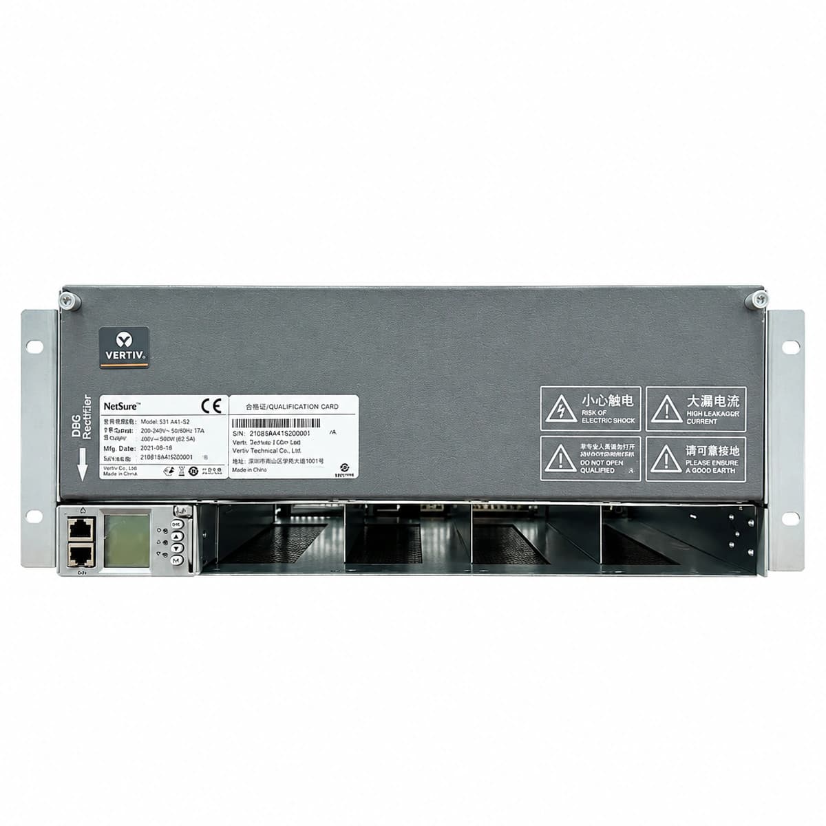
The Vertiv NetSure 531 A41-S2 is an ultra-compact 5U 19-inch rack-mount embedded telecom power system engineered to deliver up to 120A (-48V DC) power, accommodating up to 6 high-efficiency rectifiers and an M221S/M522S controller for mission-critical edge sites and wireless access nodes.

Equipment information

Brand
Vertiv
Equipment model
NetSure 531 A41-S2
Equipment type
DC power systems
Controller / software version
Confirm against the installed equipment
View full product specifications
Vertiv NetSure 531 A41-S2 5U Embedded Telecom Power System 120A (-48V DC) Official Studio Photo 3

Information below comes from the current product catalogue. Confirm the controller, software version and configuration of the installed equipment separately.

Physical Form Factor
5U 19-inch Standard Subrack Chassis
DC Distribution Branches
Battery: 2×63A + Multi-Channel MCB Load Branches
AC Input Voltage Range
85V AC ~ 300V AC
Operating Temperature
-40°C to +65°C
System Comprehensive Efficiency
≥ 96% (High Efficiency Rectification)
System Output Capacity
120A (-48V DC)

Alarms & troubleshooting

AC_FAIL (Mains Failure / AC Input Interrupted)
Controller RUN LED off, Alarm LED solid RED; Rectifier AC power LED off, Fault LED solid RED
Grid outage, upstream AC input circuit breaker tripped, or open-circuit phase/voltage dropped below 80VAC operating threshold
1. Inspect NetSure 531 AC input breaker position; verify ATS and utility grid status. 2. Measure terminal voltage between L and N using a DMM (valid operating range: 85VAC to 290VAC). 3. Restore AC supply; if alarm persists with valid mains, inspect the AC sensing board and SPD surge arrester module.
R_HVSD (Rectifier High Voltage Shutdown / Overvoltage Lockout)
Affected rectifier Yellow LED steady or off, Fault RED LED solid on, DC output disabled
Rectifier internal voltage regulation circuit breakdown, internal feedback failure causing DC bus >59.5V triggering hardware latch-off, or active load sharing loop failure
1. Identify the specific locked-out rectifier slot/module ID on the controller display. 2. Extract the faulty module, disconnect its AC supply for 60 seconds (discharging internal bus capacitors), then reseat. 3. If the module trips into HVSD immediately upon restart, replace the defective rectifier module (e.g., R48-2000e3).
DC_UNDER_VOLT / LLVD (DC Bus Undervoltage & Low Load Disconnect)
Controller CRITICAL Alarm RED LED solid on, buzzer active, LLVD DC contactor status indicates OPEN
Extended mains outage causing battery string depletion below LLVD threshold (default 43.2V–45.0V), or insufficient rectifier capacity to support current DC load
1. Immediately connect emergency generator/mobile DC power supply to restore system input. 2. Verify on the controller that the LLVD contactor opened to shed secondary loads and protect critical transmission core. 3. Once AC is restored, verify boost charge and battery current limit settings (recommended 0.1C10–0.15C10) to avoid rectifier overload.
COMM_FAIL (Rectifier CAN-bus Communication Loss)
Controller Warning Yellow LED on; affected rectifier Green RUN LED flashes rapidly (0.5s interval, autonomous mode)
Backplane CAN ribbon cable loose, gold-finger pin bent/oxidized, CAN terminating resistor missing, or slot address conflict
1. Inspect the ribbon cable linking the controller (e.g., M221S/M522S) to the subrack backplane. 2. Hot-swap out the disconnected rectifier; inspect backplane connector pins for physical damage or dust, and reseat firmly. 3. Execute 'Re-register Module' via controller; if all rectifiers drop off, test resistance between CAN_H and CAN_L (nominal: 60Ω).
R_FAN_FAIL (Rectifier Fan Blocked / Thermal Derating)
Rectifier Yellow LED solid on, controller displays Rectifier Fan Alarm, module output capacity derated
Front air dust filter clogged, foreign debris stalling fan blades, internal PWM speed control circuit failure, or tachometer feedback loss
1. Inspect NetSure 531 front air intake grilles and rectifier faceplates; clear dust build-up. 2. Extract the module; check fan blades for foreign objects or physical friction; spin manually to verify free movement. 3. Reseat the module; if the fan fails to spin up during self-test, replace the fan assembly or swap the entire rectifier unit.

Access Complete Maintenance & Full Alarm Troubleshooting Manual

This page lists high-frequency critical alarm codes commonly encountered in field maintenance. Comprehensive manufacturer troubleshooting matrices, board-level repair guides, detailed electrical schematics, and firmware commissioning manuals are delivered alongside equipment upon formal project procurement, accompanied by dedicated FAE technical support.

Share on-site information

  1. 01

    Identify the exact model

    Record the nameplate, system model and controller or module model.

  2. 02

    Keep the alarm details

    Record the full alarm text, indicator colour, timing and whether it persists.

  3. 03

    Describe recent changes

    Note recent replacements, software updates or configuration changes.

Record information visible in the existing interface. Electrical measurements, disassembly and replacement should follow the applicable manufacturer's manual and be performed by qualified personnel.

Your model and these details will be added to the enquiry form for you to review before sending.

Related technical articles

Browse the technical guides or send a question about this model.

View all articles

Need a replacement module or supporting equipment?

Confirm the full model, system configuration and compatibility requirements before enquiring about suitable products.

Ask about suitable products

Have a model and an on-site issue?

Share the exact model, alarm text and observed symptoms to help identify relevant information and compatibility requirements.

Request technical support