Vertiv / Power management

NetSure 211 C12-S1 Equipment information & support

The Vertiv NetSure 211 C12-S1 is a high-density, 19-inch rack-mounted 2U subrack -48V DC power system engineered for telecom access nodes, hosting up to three high-efficiency rectifiers and a centralized controller.

Equipment information

Brand
Vertiv
Equipment model
NetSure 211 C12-S1
Equipment type
Power management
Controller / software version
Confirm against the installed equipment
View full product specifications
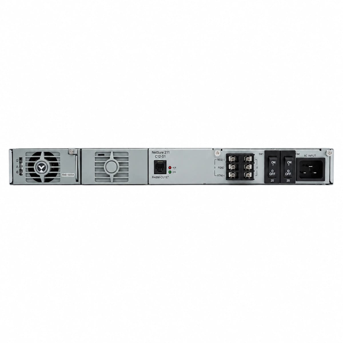
Vertiv NetSure 211 C12-S1 Official White Background Photo View 1

Information below comes from the current product catalogue. Confirm the controller, software version and configuration of the installed equipment separately.

AC Input Voltage Range
85VAC ~ 300VAC (Nominal 220VAC) VAC
Smart Monitoring Controller
M221S / M222S Smart Controller
Cooling Method
Temperature-controlled Forced Air Cooling
Nominal Output Voltage
-48VDC VDC
Rated Output Current
120A (Rated Capacity 5.8kW)
Managed Rectifier Capacity
Supports 4 × R48-1000e / R48-2000e3 Modules

Alarms & troubleshooting

AC_FAIL
Red ALARM LED solid on controller; yellow AC Fault LED lit on rectifiers
AC utility mains interruption, input voltage dropped below 85VAC, or upstream AC breaker tripped
1. Measure incoming AC voltage at terminal block with multimeter; 2. Inspect upstream ATS switchgear and subrack input MCBs; 3. Verify standby generator start and monitor remaining battery backup reserve runtime.
RECT_COMM_FAIL
Yellow ALARM LED flashing on controller; green operational LED on faulty rectifier blinking or unlit
CAN bus interface loose on backplane, golden finger connector oxidized, or internal rectifier MCU logic failure
1. Unlatch faulty rectifier, inspect backplane connector pins/clean debris, and firmly re-seat module; 2. Trigger auto-addressing scan via NCU menu; 3. Swap to adjacent slot or replace module if failure persists.
DC_VOLT_LOW
Red CRITICAL LED solid on controller, accompanied by continuous acoustic buzzer
Battery string discharging past pre-alarm threshold (default -45.0VDC) during mains outage, or severe DC bus overload
1. Verify if AC grid has restored, deploy emergency portable generator immediately if not; 2. Audit DC distribution branches for unexpected overloading; 3. Prepare for impending LLVD trip to isolate non-priority loads.
BATT_TEMP_HIGH
Yellow OBSERVATION/WARNING LED illuminated on controller
HVAC failure in battery compartment, extreme ambient temperature, or internal cell failure causing thermal runaway (>55°C)
1. Scan individual battery blocks with an infrared pyrometer to locate localized thermal hot spots; 2. Verify compartment cooling fans/HVAC operation; 3. Temporarily lower float voltage to -51.5VDC via NCU or abort boost charge.
BLVD_TRIP
Red CRITICAL LED solid on controller; contactor auxiliary contact closed triggering remote telemetry
Battery bank reached terminal discharge cutoff (default -43.2VDC), triggering contactor disconnection to protect cells
1. Do not manually bypass the BLVD contactor under load; 2. Restore primary AC power or connect mobile diesel generator; 3. Rectifiers will power the bus first upon AC restoration, then automatically reconnect the battery string under controlled charging current limits.

Access Complete Maintenance & Full Alarm Troubleshooting Manual

This page lists high-frequency critical alarm codes commonly encountered in field maintenance. Comprehensive manufacturer troubleshooting matrices, board-level repair guides, detailed electrical schematics, and firmware commissioning manuals are delivered alongside equipment upon formal project procurement, accompanied by dedicated FAE technical support.

Share on-site information

  1. 01

    Identify the exact model

    Record the nameplate, system model and controller or module model.

  2. 02

    Keep the alarm details

    Record the full alarm text, indicator colour, timing and whether it persists.

  3. 03

    Describe recent changes

    Note recent replacements, software updates or configuration changes.

Record information visible in the existing interface. Electrical measurements, disassembly and replacement should follow the applicable manufacturer's manual and be performed by qualified personnel.

Your model and these details will be added to the enquiry form for you to review before sending.

Related technical articles

Browse the technical guides or send a question about this model.

View all articles

Need a replacement module or supporting equipment?

Confirm the full model, system configuration and compatibility requirements before enquiring about suitable products.

Ask about suitable products

Have a model and an on-site issue?

Share the exact model, alarm text and observed symptoms to help identify relevant information and compatibility requirements.

Request technical support