Vertiv / Power distribution units (PDU)

Liebert UF-LTS32-1P Equipment information & support

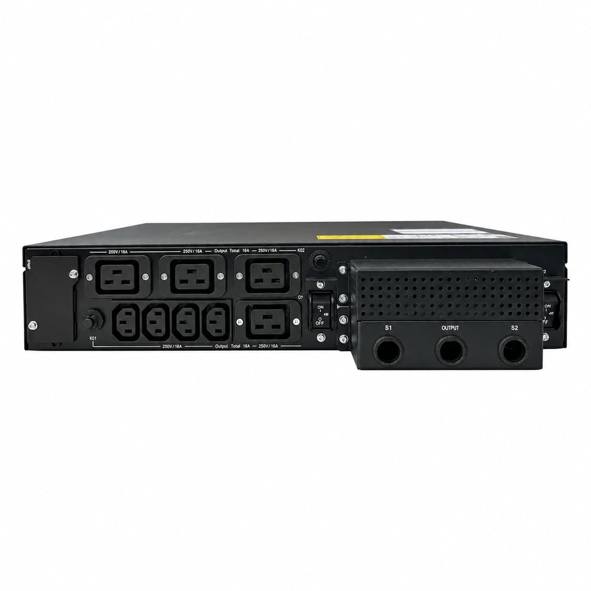
The Vertiv Liebert LTS 32A (UF-LTS32-1P) is a high-speed 1U rackmount single-phase static transfer switch rated at 32A delivering seamless power transfer (<6ms) between two independent AC sources for single-corded IT equipment.

Equipment information

Brand
Vertiv
Equipment model
Liebert UF-LTS32-1P
Equipment type
Power distribution units (PDU)
Controller / software version
Confirm against the installed equipment
View full product specifications
Liebert UF-LTS32-1P Official Product View 1

Information below comes from the current product catalogue. Confirm the controller, software version and configuration of the installed equipment separately.

Rated Switching Current
32 A
Rated DC Operating Voltage
220 / 230 / 240 VAC
Transfer Time
< 6 (ultra-fast seamless transfer) ms
Input Channels
Dual independent AC utility / UPS power inputs with redundant mutual backup
Physical Form Factor
1U standard 19-inch rack-mount
Physical Dimensions Spec
43.5 × 435 × 250 mm (1U)

Alarms & troubleshooting

SRC1_FAIL (Source 1 Input Abnormal/Loss)
S1 LED off or red flashing, Fault LED solid red, S2 powering load
Source 1 breaker open, upstream AC mains loss, or input voltage/frequency out of transfer threshold (180V-264V).
1. Check the upstream distribution breaker for Source 1. 2. Measure L-N voltage and frequency at S1 input terminals using a true-RMS multimeter. 3. If input is within spec, inspect LTS terminal block wiring integrity and clear the alarm via the control panel.
SRC2_FAIL (Source 2 Input Abnormal/Loss)
S2 LED off or red flashing, Warning LED lit, power redundancy lost
Source 2 standby power failure, input breaker trip, undervoltage/overvoltage, loss of transfer redundancy.
1. Immediately check upstream circuit breaker and health of Source 2 (secondary UPS/Mains). 2. Verify S2 terminal voltage is within configured tolerances. 3. Do not perform manual maintenance or switching on Source 1 until Source 2 redundancy is restored.
OUT_OVERLOAD (Output Current Overload)
Overload LED solid amber/red, audible alarm sounds continuously
Load current exceeds UF-LTS32 continuous rated capacity (32A), severe downstream IT inrush, or rack PDU circuit overloaded.
1. Read real-time output current (Amps) on the front display or Web/SNMP interface. 2. Immediately shed non-critical rack IT loads to bring total current below 25A (80% continuous rating). 3. Balance downstream PDU branch circuits and avoid triggering any manual or automatic source transfers during overload.
PHASE_UNSYNC (Input Sources Out-of-Sync/Phase Mismatch)
Sync LED amber flashing or off, Transfer Inhibit status active
Phase angle difference between S1 and S2 exceeds safe limit (>30°), sources derived from unsynchronized grids, or asynchronous UPS feeds.
1. Check the phase angle delta between S1 and S2 on the LTS monitor screen. 2. Confirm upstream UPS load sync bus (LBS) cabling and sync operation are functional. 3. If sources cannot be synchronized, evaluate STS configuration for allowable asynchronous transfer mode (break-before-make) versus risk of inrush current to downstream transformers.
SCR_FAULT (Thyristor / SCR Short or Open Circuit)
Fault LED solid red, Transfer Inhibit LED on, transfer locked on current source
Internal solid-state silicon-controlled rectifier (SCR) shorted/open, gate drive failure, or internal power switching stage hardware fault.
1. DO NOT attempt manual source transfer; a shorted SCR can bridge asynchronous AC sources and trigger a catastrophic phase-to-phase arc fault. 2. Ensure the active powering line is stable; engage downstream wrap-around maintenance bypass if available. 3. Completely isolate the UF-LTS32-1P by opening input/output breakers and replace the defective static transfer switch unit.

Access Complete Maintenance & Full Alarm Troubleshooting Manual

This page lists high-frequency critical alarm codes commonly encountered in field maintenance. Comprehensive manufacturer troubleshooting matrices, board-level repair guides, detailed electrical schematics, and firmware commissioning manuals are delivered alongside equipment upon formal project procurement, accompanied by dedicated FAE technical support.

Share on-site information

  1. 01

    Identify the exact model

    Record the nameplate, system model and controller or module model.

  2. 02

    Keep the alarm details

    Record the full alarm text, indicator colour, timing and whether it persists.

  3. 03

    Describe recent changes

    Note recent replacements, software updates or configuration changes.

Record information visible in the existing interface. Electrical measurements, disassembly and replacement should follow the applicable manufacturer's manual and be performed by qualified personnel.

Your model and these details will be added to the enquiry form for you to review before sending.

Related technical articles

Browse the technical guides or send a question about this model.

View all articles

Need a replacement module or supporting equipment?

Confirm the full model, system configuration and compatibility requirements before enquiring about suitable products.

Ask about suitable products

Have a model and an on-site issue?

Share the exact model, alarm text and observed symptoms to help identify relevant information and compatibility requirements.

Request technical support