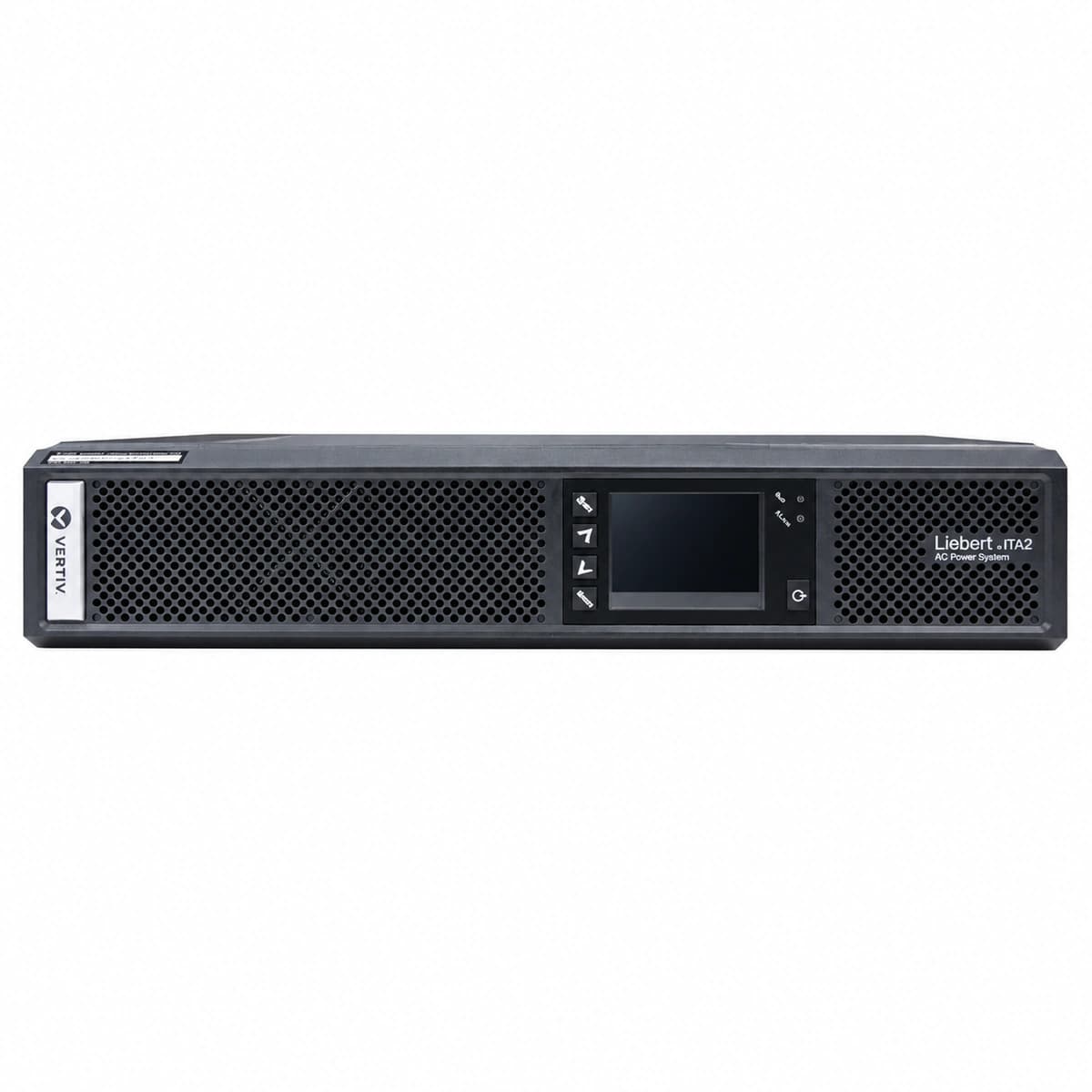
Vertiv Liebert ITA2 6kVA is a high-performance rackmount online double-conversion UPS featuring unity power factor (PF=1.0, 6kW) and full digital DSP architecture.
Information below comes from the current product catalogue. Confirm the controller, software version and configuration of the installed equipment separately.
Fault LED solid Red, Inverter LED off, Bypass LED solid Amber, continuous audible alarm
Inverter bridge IGBT short/breakdown, DC bus transient overvoltage, output AC voltage feedback drift, or gate drive circuit failure
1. Review LCD sub-alarm event history to verify if caused by DC bus overvoltage or inverter hardware overcurrent.
2. Verify the static bypass line parameters are within tolerance and holding the critical load safely.
3. Turn off output load, perform software shutdown, and open AC input and external battery circuit breakers.
4. Wait 5 minutes for DC link bus capacitors to discharge below 36 Vdc. Measure IGBT bridge pole-to-ground resistance and phase impedance. Replace power PCB assembly if short-circuit is detected, then re-commission.
BATT_EOD (Battery End of Discharge Shutdown)
Battery LED flashes Amber (1Hz) then extinguishes, Fault LED solid Red, rapid intermittent buzzer
Prolonged mains blackout depleting battery bank to cutoff voltage threshold (1.67V–1.75V/cell), or external battery breaker tripped during discharge
1. Verify utility AC input status and restore primary distribution feed as priority.
2. Inspect external battery rack breaker; measure total open-circuit string voltage and verify polarity.
3. Once AC mains returns, close battery circuit breaker; verify rectifier restarts and enters float/boost charging.
4. If DC voltage fails to recover, perform single-block internal resistance tests to identify deteriorated blocks; replace worn cells and recalibrate EOD parameters via LCD/web card.
OVER_TEMP (Internal Heatsink Over-Temperature)
Fault LED solid Red, Bypass LED solid Amber, intermittent buzzer sound every 0.5s
Ambient temperature exceeding 40°C spec, ventilation slots/air filters clogged with dust, NTC thermistor sensor fault, or total cooling fan stall
1. Verify data center precision air conditioning and bring rack ambient air intake down to 20°C–25°C.
2. Inspect front and rear ventilation grilles and filters; remove dust obstructions and ensure ≥200 mm clearance.
3. Check LCD real-time temperature telemetry; if ambient is cold but reading is pinned >95°C, inspect and replace the faulty NTC harness.
4. Allow unit to cool down and clear thermal latch; if temperatures rapidly spike upon restart under normal load, inspect thermal interface paste on power modules.
OUTPUT_OVERLOAD (Output Overload Bypass Active)
Overload warning icon flashing, Bypass LED solid Amber, Inverter LED off, continuous buzzer alarm
Downstream IT load inrush current surge or total connected active power exceeding rated 6kVA/6kW capacity (>105% timed transfer, >130% immediate bypass)
1. Check LCD load bar and telemetry page to inspect output phase current and total Load percentage (VA/Watt).
2. Shed non-critical IT equipment loads on branch PDUs until total connected load is below 80% capacity.
3. Wait for the internal thermal overload timer to clear, then command "Inverter Turn ON" via the LCD menu to transfer back to normal mode.
4. If real load is well below 6kVA but alarm persists, verify output current transformer (CT) zero-point calibration and replace the sensor board if reading drifts.
FAN_FAULT (Cooling Fan Locked Rotor / Speed Abnormal)
Fault LED solid Amber, LCD Fan fault icon blinking, audible buzzer beeps once every 1s
Cooling fan bearing physically jammed by debris, missing PWM tachometer feedback pulse, loose fan cable connector, or driver circuit failure on control PCB
1. Visually inspect rear exhaust fan bank to identify which specific fan has stopped rotating or is spinning below rated RPM.
2. Use compressed dry air to clear dust; manually spin fan blades with unit off to verify smooth mechanical rotation without bearing friction.
3. Follow electrical safety lock-out procedures, open top cover, and verify that fan harness Molex connectors on power board are firmly seated.
4. Measure DC supply across fan headers (nominal 12V–24Vdc) and tachometer feedback pin; if drive voltage is present but fan does not run, replace the fan assembly with OEM spare.
Access Complete Maintenance & Full Alarm Troubleshooting Manual
This page lists high-frequency critical alarm codes commonly encountered in field maintenance. Comprehensive manufacturer troubleshooting matrices, board-level repair guides, detailed electrical schematics, and firmware commissioning manuals are delivered alongside equipment upon formal project procurement, accompanied by dedicated FAE technical support.
Record the nameplate, system model and controller or module model.
02
Keep the alarm details
Record the full alarm text, indicator colour, timing and whether it persists.
03
Describe recent changes
Note recent replacements, software updates or configuration changes.
Record information visible in the existing interface. Electrical measurements, disassembly and replacement should follow the applicable manufacturer's manual and be performed by qualified personnel.
Related technical articles
Browse the technical guides or send a question about this model.