Vertiv / UPS power

Liebert ITA-BCI0020k02 Equipment information & support

The Vertiv Liebert ITA-BCI0020k02 is a 3U rack/tower convertible high-density external battery cabinet engineered specifically for Liebert ITA2 5kVA~20kVA UPS systems, equipped with heavy-duty quick-connect Anderson power connectors.

Equipment information

Brand
Vertiv
Equipment model
Liebert ITA-BCI0020k02
Equipment type
UPS power
Controller / software version
Confirm against the installed equipment
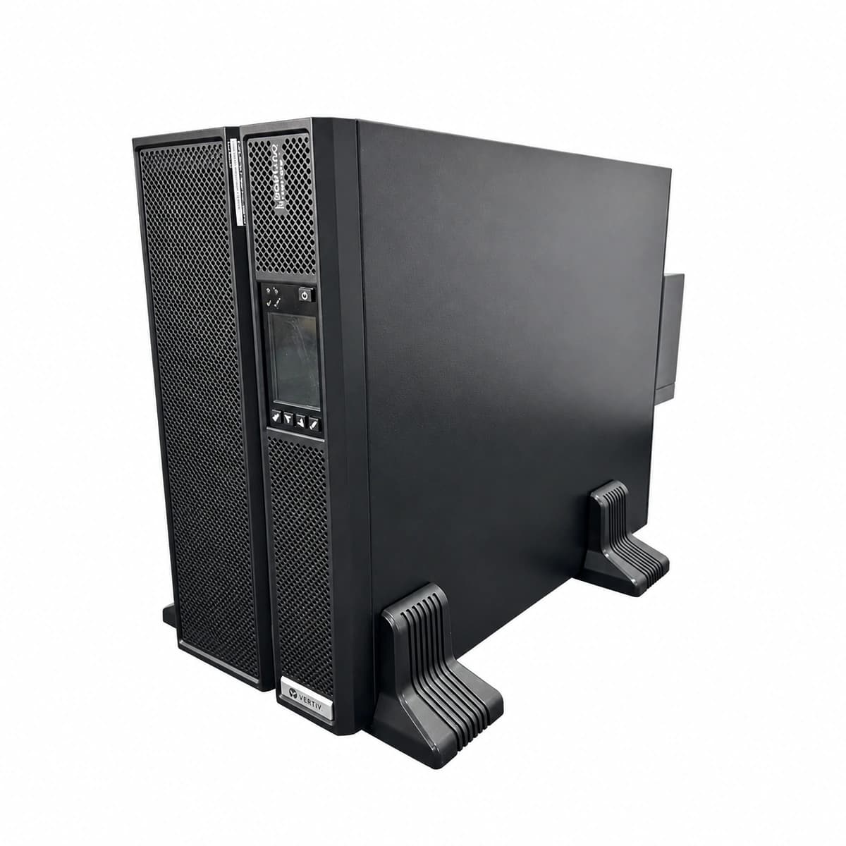
View full product specifications
Liebert ITA-BCI0020k02 Official Product View 4

Information below comes from the current product catalogue. Confirm the controller, software version and configuration of the installed equipment separately.

Apparent Power
Compatible with ITA/ITA2 10kVA/16kVA/20kVA systems VA
Active Power
DC bus rated to support ±120V / ±144V / ±192V DC
Output Power Factor PF
Supports a flexible built-in configuration of 16~20 batteries
Physical Form Factor
3U standard 19-inch rack-mount / horizontal tower form factor
Physical Dimensions Spec
130 × 435 × 650 mm (3U)
Operating Temperature
0°C to +40°C

Alarms & troubleshooting

BATT_BRK_OPEN (Battery Breaker Open)
UPS Fault LED solid red, Battery LED off, continuous audible buzzer
Internal DC breaker manually opened, tripped on DC overcurrent, or auxiliary contact wiring disconnected
1. Check if the ITA-BCI0020k02 breaker handle is in the OFF/TRIP position. 2. Use a multimeter to verify there is no short circuit or insulation fault on the DC bus. 3. Inspect the auxiliary contact signaling cable to the UPS. 4. Clear any short circuit fault and manually reset the breaker to ON.
BATT_LOW_VOLT (Battery Under-Voltage / EOD)
UPS Warning LED blinking amber (turns solid red near EOD), battery capacity bar shows 1 bar or blinking
Extended AC outage causing deep discharge to cutoff threshold, or defective open-circuit cell causing bus voltage drop
1. Restore AC utility to recharge the battery; if EOD is reached, allow rectifier float recharge. 2. Measure individual 12V block voltages under static load; identify degraded blocks (<10.5V). 3. Torque busbar terminals to 4.5-5.5 N·m. 4. Replace aged blocks and perform battery calibration discharge.
BATT_OVER_TEMP (Battery Enclosure Over-Temperature)
UPS Warning LED solid amber, temperature icon lit, charge current automatically derates
Damaged internal NTC temperature sensor, room HVAC failure (>40°C ambient), or battery thermal runaway
1. Check room cooling and battery module ventilation; maintain ambient at 20°C-25°C. 2. Use an infrared thermometer to scan individual blocks for bulging/overheating (>50°C requires opening breaker). 3. Check NTC temperature sensor resistance against nominal curve. 4. Isolate and replace any swollen or leaking batteries immediately.
BATT_REV_POL (DC Bus Polarity Reversed)
UPS Fault LED rapid blinking red, inverter startup inhibited, high-frequency intermittent beeping
DC power harness (+, -, N/PE) between battery cabinet and UPS cross-connected during installation or maintenance
1. Do NOT close the breaker! Immediately disconnect the ITA-BCI0020k02 breaker and UPS input. 2. Use a digital multimeter on DC range to verify open-circuit polarity at the connector. 3. Re-terminate BAT+, BAT-, and Neutral connections according to labeling. 4. Verify correct polarity and cable insulation before reconnecting.
BATT_COMM_FAIL (Battery Sense / Aux Comm Fault)
UPS Warning LED flashing amber, LCD shows battery disconnected or unable to read battery box ID/parameters
Battery enclosure sense cable/ribbon loose or disconnected, pins oxidized/bent, or aux monitor board failure
1. Check the signal cable between the rear sense port of ITA-BCI0020k02 and the UPS. 2. Unplug connector and inspect RJ45/terminal pins for oxidation, bent pins, or damage. 3. Measure aux contact resistance with a multimeter (should be <1Ω when breaker is closed). 4. Replace defective communication wiring harness or auxiliary PCB.

Access Complete Maintenance & Full Alarm Troubleshooting Manual

This page lists high-frequency critical alarm codes commonly encountered in field maintenance. Comprehensive manufacturer troubleshooting matrices, board-level repair guides, detailed electrical schematics, and firmware commissioning manuals are delivered alongside equipment upon formal project procurement, accompanied by dedicated FAE technical support.

Share on-site information

  1. 01

    Identify the exact model

    Record the nameplate, system model and controller or module model.

  2. 02

    Keep the alarm details

    Record the full alarm text, indicator colour, timing and whether it persists.

  3. 03

    Describe recent changes

    Note recent replacements, software updates or configuration changes.

Record information visible in the existing interface. Electrical measurements, disassembly and replacement should follow the applicable manufacturer's manual and be performed by qualified personnel.

Your model and these details will be added to the enquiry form for you to review before sending.

Related technical articles

Browse the technical guides or send a question about this model.

View all articles

Need a replacement module or supporting equipment?

Confirm the full model, system configuration and compatibility requirements before enquiring about suitable products.

Ask about suitable products

Have a model and an on-site issue?

Share the exact model, alarm text and observed symptoms to help identify relevant information and compatibility requirements.

Request technical support