Vertiv / UPS power

Liebert GXT5-48VBatkit Equipment information & support

The Vertiv Liebert GXT5-48VBatkit (GXT5-EBC48VRT2U) is a 2U rack/tower convertible 48V DC external battery cabinet designed to deliver scalable extended runtime for Liebert GXT5 1.5kVA to 3kVA UPS models.

Equipment information

Brand
Vertiv
Equipment model
Liebert GXT5-48VBatkit
Equipment type
UPS power
Controller / software version
Confirm against the installed equipment
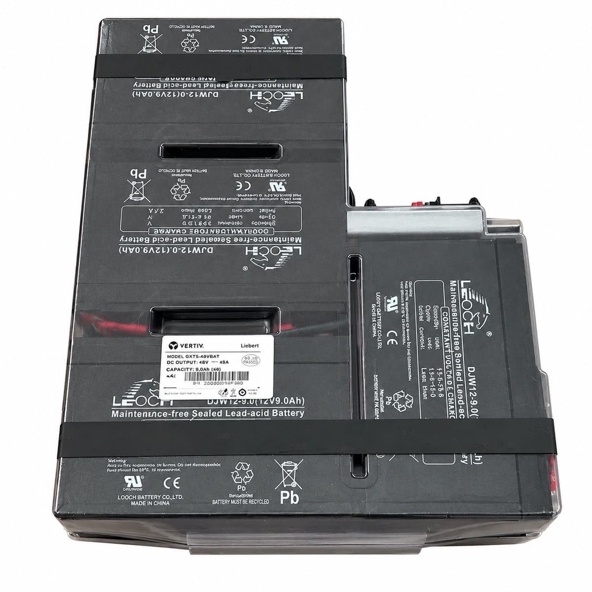
View full product specifications
Liebert GXT5-48VBatkit Official Product View 2

Information below comes from the current product catalogue. Confirm the controller, software version and configuration of the installed equipment separately.

Apparent Power
Compatible with GXT5 1500VA/2000VA models
Active Power
Rated DC bus voltage 48V DC
Output Power Factor PF
Built-in 8 12V 9Ah high-energy-density rechargeable batteries
Topology
Equipped with a dedicated DC anti-arcing circuit breaker and quick-connect interface
Physical Form Factor
2U standard 19-inch universal rack/tower form factor
Physical Dimensions Spec
85 × 430 × 490 mm (2U)

Alarms & troubleshooting

BATT_DISCON (Battery Disconnected Fault)
UPS Fault LED solid Red, Battery warning icon flashing on LCD
48V DC quick-connect terminal unseated; internal inline DC fuse blown; loose inter-tier wire harness or open-circuit bus detected.
1. Remove front/rear bezel and ensure the Anderson 48V DC quick-connect cable is fully seated and locked. 2. Disconnect the plug and measure the open-circuit voltage at the connector terminals using a DMM (normal: 48V-54Vdc). 3. If 0V is read, open the Batkit enclosure cover, verify inter-cell wiring harness continuity and internal inline DC fuse integrity; reseat terminals or replace fuse.
BATT_REPLACE (Battery Self-Test Failure / Replacement Required)
UPS Alarm LED solid Amber, LCD displays Battery Service cross icon with periodic chirp
Internal VRLA cell sulfation or dry-out causing excessive internal impedance; battery bus voltage dropped below threshold during automated self-test under load.
1. Verify UPS utility AC input is stable; allow battery to float-charge for at least 24 hours to eliminate false alerts. 2. Initiate a manual Battery Self-Test via the UPS front LCD menu. 3. If test fails again, slide out the GXT5-48VBatkit, measure each of the four 12V blocks under momentary load; if block divergence exceeds 0.5Vdc, replace the complete Batkit module.
BATT_LOW_WARN (Battery Low / End of Discharge Pre-Alarm)
UPS Battery LED flashing Amber (rapid 2Hz), buzzer beeps every 0.5s
Prolonged mains outage; battery pack discharged close to cutoff threshold (<42.0Vdc total bus / <10.5Vdc per cell block); excessive connected load depleting capacity prematurely.
1. Immediately broadcast shutdown signals via network management (NMC) to initiate graceful shutdown of connected servers and telecom switches. 2. When utility power is restored, confirm UPS transfers back to Normal Inverter mode and initiates current-limited recharge. 3. Do not attempt UPS cold-starts until AC mains is restored to prevent deep-discharge cell reversal damage.
BATT_OVERTEMP (Battery Pack Over-Temperature)
UPS Alarm LED solid Amber, LCD displays Over-Temperature warning icon
Ambient rack temperature exceeds 40°C; UPS chassis cooling airflow obstructed by dust; internal short circuit in aged VRLA cell initiating thermal runaway during charging.
1. Inspect rack air conditioning and front/rear perforated door airflow, ensuring ambient temp is maintained at 20°C-25°C. 2. Clean dust accumulation from UPS front bezel air inlets and rear exhaust fan grilles. 3. Disconnect battery kit and physically inspect for localized heat spots, bulging, or acid venting odors; replace the entire GXT5-48VBatkit immediately if physical swelling is found.
BATT_OVERVOLT (Battery Bus Overvoltage Fault)
UPS Fault LED solid Red, continuous audible alarm, UPS transfers to Bypass
UPS internal charger/rectifier regulation loop failure; float voltage surges above 58.0Vdc; incorrect voltage external battery cabinet connected (e.g., mismatched 72V EBC plugged into 48V port).
1. Immediately disconnect the GXT5-48VBatkit DC plug to isolate the pack and prevent VRLA safety valve venting or thermal casing rupture. 2. Measure the open-circuit DC charger voltage at the UPS battery terminal port using a calibrated DMM (normal 48V system float is 54.0V-54.8Vdc at 25°C). 3. If charger output persists above 56.5Vdc, the UPS power board/charger circuit is compromised; schedule UPS main chassis service/replacement.

Access Complete Maintenance & Full Alarm Troubleshooting Manual

This page lists high-frequency critical alarm codes commonly encountered in field maintenance. Comprehensive manufacturer troubleshooting matrices, board-level repair guides, detailed electrical schematics, and firmware commissioning manuals are delivered alongside equipment upon formal project procurement, accompanied by dedicated FAE technical support.

Share on-site information

  1. 01

    Identify the exact model

    Record the nameplate, system model and controller or module model.

  2. 02

    Keep the alarm details

    Record the full alarm text, indicator colour, timing and whether it persists.

  3. 03

    Describe recent changes

    Note recent replacements, software updates or configuration changes.

Record information visible in the existing interface. Electrical measurements, disassembly and replacement should follow the applicable manufacturer's manual and be performed by qualified personnel.

Your model and these details will be added to the enquiry form for you to review before sending.

Related technical articles

Browse the technical guides or send a question about this model.

View all articles

Need a replacement module or supporting equipment?

Confirm the full model, system configuration and compatibility requirements before enquiring about suitable products.

Ask about suitable products

Have a model and an on-site issue?

Share the exact model, alarm text and observed symptoms to help identify relevant information and compatibility requirements.

Request technical support