Vertiv / UPS power

Liebert GXT5 16kVA Equipment information & support

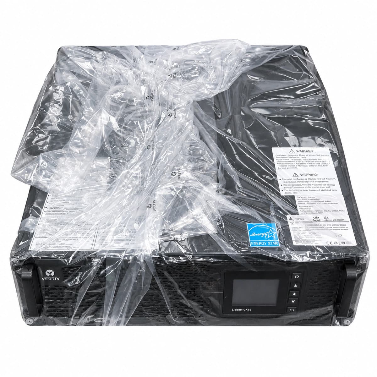
The Vertiv Liebert GXT5 16kVA (GXT5-16KIRT9UXLE) is a 9U rackmount high-capacity online double-conversion UPS delivering unity power factor (16kVA/16kW) for mission-critical blade servers and HPC clusters.

Equipment information

Brand
Vertiv
Equipment model
Liebert GXT5 16kVA
Equipment type
UPS power
Controller / software version
Confirm against the installed equipment
View full product specifications
Liebert GXT5 16kVA Official Product View 3

Information below comes from the current product catalogue. Confirm the controller, software version and configuration of the installed equipment separately.

Apparent Power
16000 VA
Active Power
16000 W
Output Power Factor PF
1.0 (Ultra-High Power Factor)
Topology
Online double-conversion, high-frequency pure sine wave
AC Input Voltage Range
176 ~ 288 VAC (full-load single-phase/three-phase compatible)
Nominal DC Output Voltage
220/230/240 VAC (single-phase adjustable)

Alarms & troubleshooting

INV_FAULT (Inverter Hardware Fault)
Alarm Red LED solid, Inverter Green LED off, Bypass Amber LED solid
Inverter IGBT breakdown, DC bus overvoltage, or internal gate drive lockout, forcing transfer to bypass
1. Verify critical loads are safely supported via static bypass. 2. Inspect the LCD panel event log and monitor recorded DC bus voltage levels. 3. Disconnect AC input and battery circuit breakers; wait 10 minutes for DC bus capacitors to discharge. 4. Measure resistance across inverter IGBT modules; if shorted, replace the power board assembly.
BATT_DISCONN (Battery Disconnected / Breaker Open)
Battery Amber LED flashing, Alarm Red LED solid, buzzer beeps once per second
External Battery Cabinet (EBC) breaker tripped/open, loose DC interconnect, or startup self-test failed to detect DC voltage
1. Check external battery cabinet circuit breakers; reset if tripped after verifying no short circuit exists. 2. Inspect DC power connectors and communication detection sense cables between UPS and EBC modules. 3. Measure battery string open-circuit voltage with a DC voltmeter to verify proper nominal potential. 4. Initiate a manual Battery Self-Test via the front LCD panel to refresh status and clear the alarm.
BATT_EOD (Battery End of Discharge / Low Voltage)
Alarm Red LED flashing rapidly, Battery Amber LED solid, continuous acoustic buzzer
Prolonged mains outage; battery discharge reached safety threshold (1.67V-1.75V/cell), triggering low-voltage cutoff
1. Verify utility AC feeder status immediately or start the auxiliary diesel generator. 2. Once AC input is restored, confirm rectifier starts and initiates controlled recharge. 3. Shed non-critical auxiliary loads to allow the charger to dedicate maximum power to battery replenishment. 4. If AC is present but error persists, test individual cell internal resistance to isolate degraded blocks.
OUTPUT_OVERLOAD (UPS Output Overload Condition)
Bypass Amber LED solid, Inverter Green LED solid or off, Alarm Red LED flashes twice per second
Connected IT equipment exceeds 16kVA/16kW rating or downline inrush current exceeded inverter limit
1. Read real-time load percentage and output apparent power on the front LCD panel. 2. Immediately disconnect non-essential loads to reduce total capacity below 80% of rated threshold. 3. Inspect downstream PDUs for localized short-circuits or phase imbalance conditions. 4. Once power draw is stabilized within limits, transfer the load back from bypass to inverter mode.
OVER_TEMP (Internal Thermal Over-Temperature)
Alarm Red LED solid, cooling fans running at full speed, system transferred to bypass
Ambient room temperature exceeds 40°C, air inlet bezel blocked with dust, ventilation failure, or cooling fan stall
1. Check room air conditioning operation to bring ambient temperature into the 20°C-25°C optimal range. 2. Inspect and clear dust obstructions from the front ventilation bezel and rear exhaust area. 3. Navigate LCD diagnostic menus to verify individual cooling fan RPMs and identify any failed units. 4. Allow internal heatsinks to cool down below threshold limits before switching back to inverter mode.

Access Complete Maintenance & Full Alarm Troubleshooting Manual

This page lists high-frequency critical alarm codes commonly encountered in field maintenance. Comprehensive manufacturer troubleshooting matrices, board-level repair guides, detailed electrical schematics, and firmware commissioning manuals are delivered alongside equipment upon formal project procurement, accompanied by dedicated FAE technical support.

Share on-site information

  1. 01

    Identify the exact model

    Record the nameplate, system model and controller or module model.

  2. 02

    Keep the alarm details

    Record the full alarm text, indicator colour, timing and whether it persists.

  3. 03

    Describe recent changes

    Note recent replacements, software updates or configuration changes.

Record information visible in the existing interface. Electrical measurements, disassembly and replacement should follow the applicable manufacturer's manual and be performed by qualified personnel.

Your model and these details will be added to the enquiry form for you to review before sending.

Related technical articles

Browse the technical guides or send a question about this model.

View all articles

Need a replacement module or supporting equipment?

Confirm the full model, system configuration and compatibility requirements before enquiring about suitable products.

Ask about suitable products

Have a model and an on-site issue?

Share the exact model, alarm text and observed symptoms to help identify relevant information and compatibility requirements.

Request technical support