Vertiv / UPS power

Liebert GXE3 6kVA Equipment information & support

The Vertiv Liebert GXE3 6kVA is an industrial-grade single-phase online double-conversion tower UPS rated at 6000VA/5400W engineered with digital DSP control and an ultra-wide AC input window.

Equipment information

Brand
Vertiv
Equipment model
Liebert GXE3 6kVA
Equipment type
UPS power
Controller / software version
Confirm against the installed equipment
View full product specifications
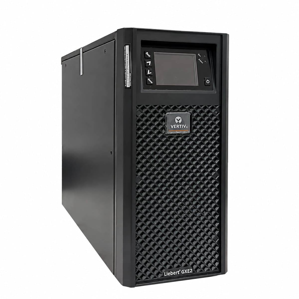
Liebert GXE3 6kVA Official Product View 1

Information below comes from the current product catalogue. Confirm the controller, software version and configuration of the installed equipment separately.

Apparent Power
6000 VA
Active Power
5400 W
Output Power Factor PF
0.9
Topology
Online double-conversion, high-frequency pure sine wave
AC Input Voltage Range
120 ~ 288 VAC
Nominal DC Output Voltage
220 VAC ± 1%

Alarms & troubleshooting

INV_FAULT (Inverter Fault)
Fault LED solid red, Inverter LED off, Bypass LED solid yellow, continuous buzzer tone
Inverter IGBT breakdown, driver board malfunction, DC bus overvoltage, or load short-circuit, triggering latch-off to bypass
1. Check secondary fault code on LCD (e.g., Bus Overvoltage or Inverter Short); 2. Disconnect output distribution breakers and inspect load circuit for short circuits; 3. Perform a complete shutdown, wait for DC bus discharge, and cold restart; 4. If fault persists, replace the power/inverter board assembly
BATT_DISC (Battery Disconnected/Open)
Warning LED blinking yellow (0.5Hz), Battery LED blinking red, beeps once per second
External battery cabinet breaker is open, DC power cable loose/unseated, battery voltage below detection threshold, or battery fuse blown
1. Verify external battery Anderson/terminal connector on the rear panel is firmly locked; 2. Close external battery circuit breaker and measure total DC terminal voltage with a multimeter (~192Vdc/240Vdc nominal); 3. Inspect battery fuses and interconnect links for looseness; 4. Execute manual 'Battery Self-Test' via LCD menu to clear alarm
OUTPUT_OVERLOAD (Output Overload)
Overload LED solid yellow or blinking red, buzzer sounds twice every 2 seconds; transfers to bypass with Bypass LED lit if duration expires
Connected IT load exceeds UPS rated capacity (>105%-150% of 6kVA/6kW), or severe inrush current on a branch circuit
1. Review Load % reading on the LCD home screen; 2. Immediately shed non-critical auxiliary loads to bring load under 80%; 3. Verify downstream PDUs for unbalanced branch loads or partial short circuits; 4. Re-transfer UPS manually from bypass back to inverter via operation menu
OVER_TEMP (Over Temperature Fault)
Fault LED solid red, Fan/Thermal alert icon active on LCD, rapid continuous buzzer
Air intake/dust filter clogged, ambient room temperature exceeding 40°C threshold, or internal cooling fan seized/RPM abnormal
1. Clean dust and remove obstructions from front air inlet and rear exhaust grilles; 2. Verify datacenter precision AC is operating and bring room temperature below 25°C; 3. Inspect rear cooling fans for rotational blockage or failure; 4. Allow unit to cool down for 30 minutes, then restart
CHG_FAULT (Charger Failure)
Warning LED solid yellow, LCD shows charger fault icon/code, intermittent buzzer beeps
Charger circuit component breakdown, charger output overvoltage cutoff triggered, or charging voltage sense loop failure
1. Check if AC input mains voltage and THD are within permissible tolerances; 2. Disconnect external battery pack and measure UPS charging port open-circuit DC voltage with a DMM; 3. Reset battery charger configuration parameters to factory default via LCD; 4. If charging output voltage is out of spec or fault persists, replace charger board assembly

Access Complete Maintenance & Full Alarm Troubleshooting Manual

This page lists high-frequency critical alarm codes commonly encountered in field maintenance. Comprehensive manufacturer troubleshooting matrices, board-level repair guides, detailed electrical schematics, and firmware commissioning manuals are delivered alongside equipment upon formal project procurement, accompanied by dedicated FAE technical support.

Share on-site information

  1. 01

    Identify the exact model

    Record the nameplate, system model and controller or module model.

  2. 02

    Keep the alarm details

    Record the full alarm text, indicator colour, timing and whether it persists.

  3. 03

    Describe recent changes

    Note recent replacements, software updates or configuration changes.

Record information visible in the existing interface. Electrical measurements, disassembly and replacement should follow the applicable manufacturer's manual and be performed by qualified personnel.

Your model and these details will be added to the enquiry form for you to review before sending.

Related technical articles

Browse the technical guides or send a question about this model.

View all articles

Need a replacement module or supporting equipment?

Confirm the full model, system configuration and compatibility requirements before enquiring about suitable products.

Ask about suitable products

Have a model and an on-site issue?

Share the exact model, alarm text and observed symptoms to help identify relevant information and compatibility requirements.

Request technical support