Vertiv / Precision air conditioning

Liebert DME12 Equipment information & support

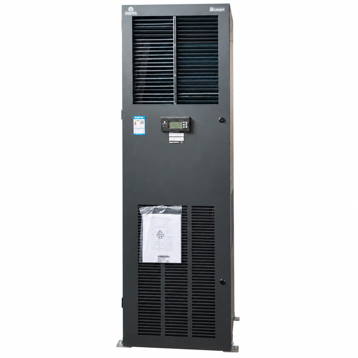
The Vertiv Liebert DME12 is a mission-critical small room precision air conditioning indoor system delivering 12.5kW total cooling with an ultra-high sensible heat ratio for 24/7 computer rooms.

Equipment information

Brand
Vertiv
Equipment model
Liebert DME12
Equipment type
Precision air conditioning
Controller / software version
Confirm against the installed equipment
View full product specifications
Liebert DME12 Official Product View 2

Information below comes from the current product catalogue. Confirm the controller, software version and configuration of the installed equipment separately.

Rated Cooling Capacity
12.5 kW
Sensible Heat Ratio (SHF)
> 0.90
Airflow Volume
3300 m³/h
Grid Power Supply System
380VAC ± 10% (3-Phase 5-Wire 50Hz)
Refrigerant Type
R410A Eco Refrigerant
Physical Dimensions Spec
1750 × 600 × 500 mm

Alarms & troubleshooting

HP_ALM (High Discharge Pressure Alarm)
Red Alarm LED solid on, buzzer sounding, compressor locked out
Outdoor condenser coil severely fouled; outdoor condenser fan failed or unpowered; condenser airflow blocked; excessive refrigerant charge; high-pressure switch defective or wiring open.
1. Inspect and clean the outdoor condenser coil with low-pressure water or fin cleaner; 2. Verify power supply and speed control output to outdoor fan; test fan capacitor and motor winding resistance; 3. Attach refrigerant manifold gauges to measure discharge pressure; check for non-condensable gases or recover excess charge; 4. Check high-pressure switch contacts (<0.1Ω nominal); press manual reset button after pressure normalizes and restart system.
LP_ALM (Low Suction Pressure Alarm)
Amber Warning LED blinking, transitions to Red Alarm LED solid on after delay and stops cooling
Refrigerant piping leakage; indoor return air filter clogged causing evaporator coil icing; thermal expansion valve (TXV) bulb charge lost or orifice restricted; liquid line filter drier blocked; low-pressure switch malfunction.
1. Inspect indoor return air filters and evaporator coil; defrost coil and clean/replace filters if restricted; 2. Observe liquid line sight glass for continuous bubbling; perform leak detection using electronic sniffer on all joints and valves; 3. Check temperature drop across the liquid line filter-drier; replace drier if delta-T exceeds 1.5°C; 4. Attach gauge manifold to measure suction pressure and superheat; adjust/replace expansion valve and recharge refrigerant per nameplate specs.
AIR_LOSS (Loss of Airflow Alarm)
Red Alarm LED solid on, electric heater, humidifier, and compressor interlocked off
Indoor EC/centrifugal fan thermal overload tripped or run capacitor failed; differential pressure switch tubing disconnected, clogged, or switch contact defective; return air inlet obstructed; blower contactor failed or phase loss.
1. Verify indoor blower AC voltage, check capacitor rating, and test motor winding continuity and isolation to ground; 2. Inspect high/low pressure sensing tubes of the airflow differential pressure switch for kinks, dust, or detachment; 3. Manually test continuity across differential pressure switch terminals when fan is running; verify actuation threshold with a digital manometer; 4. Inspect blower motor contactor and controller digital input wiring; reset thermal overload and initiate test run.
WATER_HIGH (Condensate High Water Alarm)
Amber Warning LED blinking, cooling and humidification interlocked off
Condensate drain line clogged by sediment/algae; condensate drain pump failed or lost power; float liquid level switch mechanically jammed in upper position by scale; insufficient drain piping slope.
1. Inspect and clear the drain pan basin, clean p-trap and flush external condensate drainage lines; 2. Inspect float switch mechanical movement; clean mineral deposits and verify contact continuity across open/closed states using a multimeter; 3. If equipped with a condensate pump, verify pump power input, clean pump internal reservoir, and test manual purge operation; 4. Clear alarm on display controller and verify proper water drainage during active cooling cycle.
COMM_FAIL (T/H Sensor Communication Failure Alarm)
Amber Warning LED solid on, LCD shows communication loss, unit defaults to failsafe mode
Return air T/H sensor RS485 communication lines loose, disconnected, or reversed polarity; DC auxiliary power supply (+12V/+24V) to sensor failed; incorrect RS485 bus termination/address dip switch setting; sensor transceiver chip damaged by surge.
1. Inspect the 4-wire shielded cable between controller and return air T/H sensor; verify tight terminal connections for A(+), B(-), and power; 2. Measure DC voltage across sensor V+ and GND terminals using a multimeter (expect 12V to 24V DC); 3. Verify DIP switch address and baud rate settings on sensor backplate match controller menu specifications; 4. If wiring and power are nominal but communication LED (RX/TX) remains dead, replace the T/H sensor assembly.

Access Complete Maintenance & Full Alarm Troubleshooting Manual

This page lists high-frequency critical alarm codes commonly encountered in field maintenance. Comprehensive manufacturer troubleshooting matrices, board-level repair guides, detailed electrical schematics, and firmware commissioning manuals are delivered alongside equipment upon formal project procurement, accompanied by dedicated FAE technical support.

Share on-site information

  1. 01

    Identify the exact model

    Record the nameplate, system model and controller or module model.

  2. 02

    Keep the alarm details

    Record the full alarm text, indicator colour, timing and whether it persists.

  3. 03

    Describe recent changes

    Note recent replacements, software updates or configuration changes.

Record information visible in the existing interface. Electrical measurements, disassembly and replacement should follow the applicable manufacturer's manual and be performed by qualified personnel.

Your model and these details will be added to the enquiry form for you to review before sending.

Related technical articles

Browse the technical guides or send a question about this model.

View all articles

Need a replacement module or supporting equipment?

Confirm the full model, system configuration and compatibility requirements before enquiring about suitable products.

Ask about suitable products

Have a model and an on-site issue?

Share the exact model, alarm text and observed symptoms to help identify relevant information and compatibility requirements.

Request technical support