Vertiv / Power management

BMK1115601-006 Equipment information & support

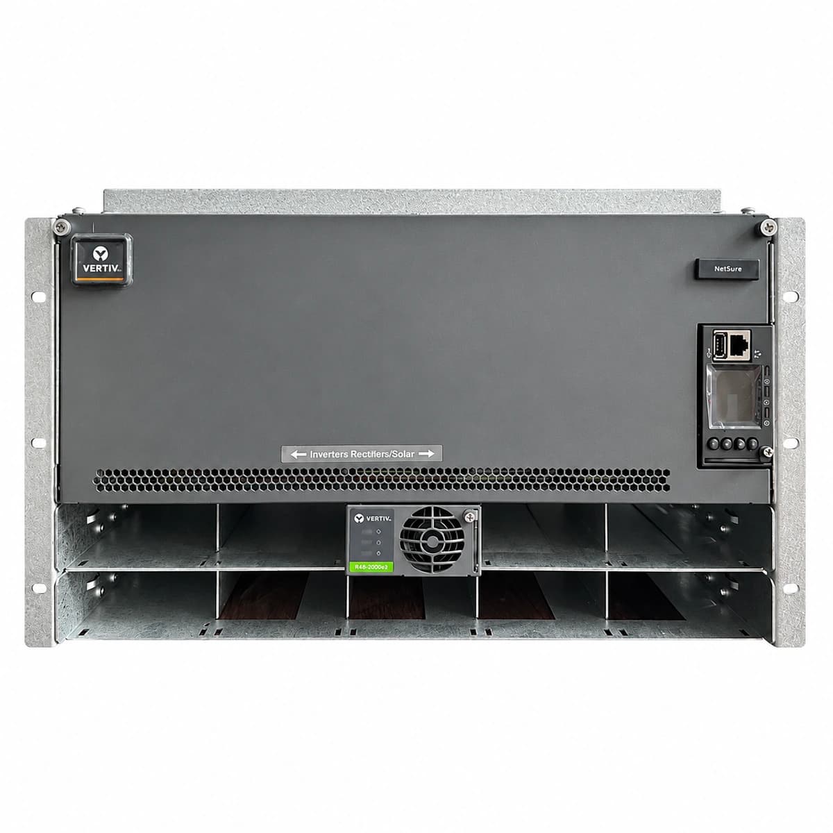
The Vertiv BMK1115601-006 is a telecom-grade -48VDC embedded switched-mode power supply (SMPS) subrack system integrating high-efficiency rectifiers, intelligent DC distribution, and supervisory control architecture.

Equipment information

Brand
Vertiv
Equipment model
BMK1115601-006
Equipment type
Power management
Controller / software version
Confirm against the installed equipment
View full product specifications
Vertiv BMK1115601-006 Official White Background Photo View 1

Information below comes from the current product catalogue. Confirm the controller, software version and configuration of the installed equipment separately.

AC Input Voltage Range
85VAC ~ 300VAC (Nominal 220VAC) VAC
Smart Monitoring Controller
M522B / M530B Monitoring Controller
Cooling Method
Front-to-rear forced air cooling
Nominal Output Voltage
-48VDC VDC
Rated Output Current
200A (System Capacity 9.6kW)
Managed Rectifier Capacity
4-Slot Standard 50A Rectifier Subrack

Alarms & troubleshooting

AC_MAINS_FAIL
Controller Major/Critical LED solid RED; Rectifier AC power LED OFF, Protection LED solid YELLOW
Utility grid blackout, AC input circuit breaker tripped, or AC voltage dropped below 85VAC cutoff limit; system operating on battery reserve.
Measure incoming AC phase voltages with a true-RMS multimeter; verify upstream ATS switch and surge protection circuit breakers; start standby diesel generator if grid outage exceeds site autonomy backup window.
DC_VOLT_LOW
Controller Critical LED flashing RED, audible buzzer active
DC bus voltage has dropped below configured undervoltage alarm threshold (typically 45.0V), indicating advanced battery discharge approaching the LLVD/BLVD cutoff points.
Immediately verify rectifier operation status; ensure modules are not in manual shutdown or severe current limitation mode; deploy mobile emergency DC/AC generator before BLVD disconnect occurs.
RECT_COMM_FAIL
Controller Major LED solid YELLOW; corresponding rectifier alarm LED flashing YELLOW
Internal CAN bus communication lost between supervisory controller and the specified rectifier slot due to loose backplane seating, broken termination resistor, or transceiver failure.
Firmly reseat the affected rectifier and verify locking latch engagement; inspect CAN cabling and terminal ribbons on the subrack backplane; execute 'Refresh/Auto-detect Rectifiers' in controller; swap module to isolate slot vs module fault.
RECT_OVER_TEMP
Rectifier Protection LED solid YELLOW, internal fan spinning at maximum RPM; controller posts WARNING status
Internal heat sink temperature has exceeded safety threshold (>75°C derating, >85°C protective shutdown), commonly caused by air filter clogging, blocked exhaust airflow, fan degradation, or room HVAC failure.
Clean or replace subrack/cabinet intake dust filters; verify that no cables or obstacles obstruct the front-to-back ventilation path; inspect rectifier fan blades for rotational clearance; ensure site ambient room temperature is restored to nominal levels.
LOAD_FUSE_BLOWN
Distribution panel circuit trip LED solid RED, controller triggers MAJOR alarm
A DC distribution fuse has blown or an MCB breaker has tripped due to field overload, branch short-circuit, or damaged auxiliary alarm sensor contacts.
Isolate the affected branch circuit; verify load wiring for low-resistance short circuits or negative-to-chassis faults using a digital multimeter; resolve downstream equipment fault before replacing with an identical rated fuse or resetting breaker; clear the alarm in the controller.

Access Complete Maintenance & Full Alarm Troubleshooting Manual

This page lists high-frequency critical alarm codes commonly encountered in field maintenance. Comprehensive manufacturer troubleshooting matrices, board-level repair guides, detailed electrical schematics, and firmware commissioning manuals are delivered alongside equipment upon formal project procurement, accompanied by dedicated FAE technical support.

Share on-site information

  1. 01

    Identify the exact model

    Record the nameplate, system model and controller or module model.

  2. 02

    Keep the alarm details

    Record the full alarm text, indicator colour, timing and whether it persists.

  3. 03

    Describe recent changes

    Note recent replacements, software updates or configuration changes.

Record information visible in the existing interface. Electrical measurements, disassembly and replacement should follow the applicable manufacturer's manual and be performed by qualified personnel.

Your model and these details will be added to the enquiry form for you to review before sending.

Related technical articles

Browse the technical guides or send a question about this model.

View all articles

Need a replacement module or supporting equipment?

Confirm the full model, system configuration and compatibility requirements before enquiring about suitable products.

Ask about suitable products

Have a model and an on-site issue?

Share the exact model, alarm text and observed symptoms to help identify relevant information and compatibility requirements.

Request technical support