Nokia / SFP optical transceivers

Nokia Flexi RRU B01-2100 Equipment information & support

Carrier-proven 2100MHz 2Tx/2Rx Remote Radio Unit for Nokia Flexi Multiradio base stations, supporting OBSAI/CPRI fiber connectivity.

Equipment information

Brand
Nokia
Equipment model
Nokia Flexi RRU B01-2100
Equipment type
SFP optical transceivers
Controller / software version
Confirm against the installed equipment
View full product specifications
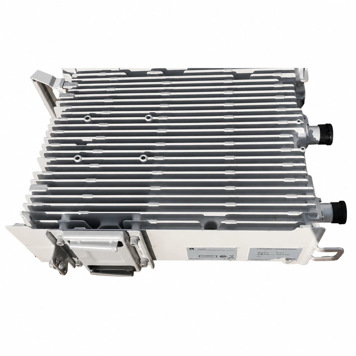
Nokia Flexi RRU B01-2100 authentic hardware perspective 1

Information below comes from the current product catalogue. Confirm the controller, software version and configuration of the installed equipment separately.

Operating Frequency Band
2100MHz (3GPP Band 1)
Antenna Tx/Rx Channels
2Tx / 2Rx dual-transceiver architecture
RF Output Power
2 × 40W / 2 × 60W software-defined output
Baseband Fiber Interfaces
Dual OBSAI / CPRI high-speed optical ports
Modular Casing Architecture
Nokia standard modular die-cast aluminum housing
DC Input Voltage Range
-48V DC (-36V to -60V DC wide range)

Alarms & troubleshooting

7654 OPT_RX_LOS (Optical Interface RX Loss of Signal)
OPT LED solid red, STATUS LED solid amber
Fiber cable break, excessive patch cord bending, dirty LC optical ferrule, or opposing BBU/FSM optical transmitter disabled/failed.
1. Inspect optical patch cord between RRU and BBU for physical pinch or tight bends. 2. Clean optical LC connectors at both RRU and BBU ports using a dry cassette/click cleaner. 3. Measure optical RX power using a calibrated optical power meter (nominal: -14 dBm to -3 dBm). 4. If optical input power is nominal, replace the SFP module in the RRU.
7653 SFP_MOD_FAIL (Optical Transceiver Module Failure)
OPT LED blinking amber at 0.5Hz, STATUS LED solid green
SFP internal EEPROM read fault, I2C bus hang-up, laser bias current exceeding failure threshold, or non-Nokia qualified SFP inserted.
1. Release the bail latch, remove the SFP module, and inspect the card edge gold fingers for damage. 2. Reseat the SFP module firmly until the latch clicks into the cage. 3. Query the BTS management CLI/WebUI to verify if the SFP part number matches the Nokia Approved Vendor List. 4. If DDM telemetry fails to load, replace the module with an approved Nokia spare.
7651 CPRI_LINK_DOWN (CPRI Link Down & Frame Sync Loss)
OPT LED blinking red at 1Hz, STATUS LED solid red
CPRI line rate mismatch between BBU and RRU (e.g. 2.4G/4.9G/9.8Gbps), optical wavelength mismatch, or CPRI basic frame sync loss.
1. Verify in BTS configuration that the CPRI rate on the BBU port matches the RRU B01 port specification. 2. Confirm that both SFP transceivers share identical wavelength specifications (e.g., both 1310nm SMF). 3. Perform optical loopback test to isolate fiber plant vs transceiver/port physical failure. 4. If rate and wavelength match, perform a soft reset of the RRU and re-initialize the BBU CPRI interface.
7655 SFP_TEMP_HIGH (SFP Module Over-Temperature Warning)
STATUS LED solid green, OPT LED solid amber
Excessive ambient temperature (>+55°C), clogged RRU heatsink fins, direct solar load without sunshield, or commercial-grade SFP installed instead of industrial-grade (-40°C to +85°C).
1. Inspect RRU housing and heatsink fins; clear any dirt, nesting materials, or blockages. 2. Ensure the Nokia outdoor solar shield is properly installed to mitigate solar radiation. 3. Query DDM diagnostics via BTS manager to read real-time SFP internal temperature (threshold: <+85°C). 4. Check SFP rating; replace commercial-grade modules with certified industrial-temp (-40°C to +85°C) transceivers.
7656 OPT_BER_HIGH (Optical Link Degraded & Bit Error Rate Exceeded)
OPT LED blinking amber at 2Hz, STATUS LED solid green
Optical receive power operating near sensitivity threshold, minor fiber end-face contamination, micro-bending inducing jitter, or transmitter aging causing eye pattern degradation.
1. Extract DDM diagnostic logs via BTS manager and compare current TX/RX power levels against baseline values. 2. Inspect optical patch connector end-faces with a fiber scope for scratches or residue, and re-clean. 3. Test the outdoor FTTA fiber run with an OTDR to detect high-loss splice points or tight cable ties. 4. If optical attenuation meets specification but CRC error counters continue to rise, replace the SFP module pair.

Access Complete Maintenance & Full Alarm Troubleshooting Manual

This page lists high-frequency critical alarm codes commonly encountered in field maintenance. Comprehensive manufacturer troubleshooting matrices, board-level repair guides, detailed electrical schematics, and firmware commissioning manuals are delivered alongside equipment upon formal project procurement, accompanied by dedicated FAE technical support.

Share on-site information

  1. 01

    Identify the exact model

    Record the nameplate, system model and controller or module model.

  2. 02

    Keep the alarm details

    Record the full alarm text, indicator colour, timing and whether it persists.

  3. 03

    Describe recent changes

    Note recent replacements, software updates or configuration changes.

Record information visible in the existing interface. Electrical measurements, disassembly and replacement should follow the applicable manufacturer's manual and be performed by qualified personnel.

Your model and these details will be added to the enquiry form for you to review before sending.

Related technical articles

Browse the technical guides or send a question about this model.

View all articles

Need a replacement module or supporting equipment?

Confirm the full model, system configuration and compatibility requirements before enquiring about suitable products.

Ask about suitable products

Have a model and an on-site issue?

Share the exact model, alarm text and observed symptoms to help identify relevant information and compatibility requirements.

Request technical support