Huawei / Indoor power systems

Huawei TP48600B-N16C1 Equipment information & support

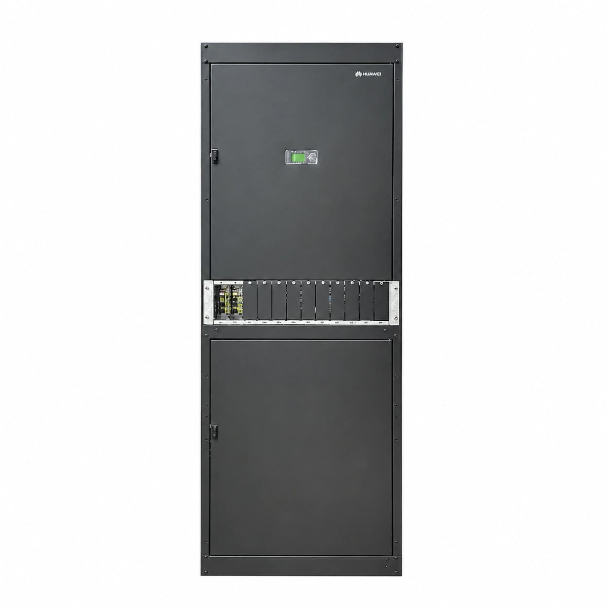
The Huawei TP48600B-N16C1 is a telecommunication-grade 600A indoor power cabinet engineered for central offices, optical nodes, and mission-critical enterprise telecom facilities. Housed in a standardized 2000×600×600 mm enclosure, it integrates AC/DC distribution, Class C lightning surge suppression, high-amperage busbars, and 12 hot-pluggable rectifier slots accommodating R4850G2 ultra-high-efficiency modules managed by a centralized SMU02C controller, delivering clean -48V DC power with up to 96% conversion efficiency under wide-range 85V–300V AC input conditions.

Equipment information

Brand
Huawei
Equipment model
Huawei TP48600B-N16C1
Equipment type
Indoor power systems
Controller / software version
Confirm against the installed equipment
View full product specifications
Huawei TP48600B-N16C1 Telecom Power Cabinet System (600A / -48V DC / 12×R4850G2 / SMU02C) Official Studio Photo 1

Information below comes from the current product catalogue. Confirm the controller, software version and configuration of the installed equipment separately.

System Output Capacity
600A (-48V DC)
AC Input Voltage Range
85V AC ~ 300V AC (3-Phase 5-Wire 380V)
Physical Form Factor
2000×600×600 mm Standard Floor-Standing Indoor Cabinet
Rectifier Module Slots
12 Slots (Compatible with 12×R4850G2 50A Rectifiers)
System Monitoring Controller
SMU02C Intelligent Network Controller Unit
System Comprehensive Efficiency
≥ 96% (High Frequency Switching Efficiency)

Alarms & troubleshooting

AC_FAIL (AC Mains Power Failure / Phase Loss)
SMU ALM LED steady red; Rectifier green RUN LED off, yellow ALM LED blinking or off
Utility grid outage, AC input voltage exceeding/dropping below operational range, tripped input MCB, or phase loss
1. Measure phase and line-to-line voltages at AC distribution input with a multimeter (standard range: 85V AC to 300V AC). 2. Inspect the upstream and internal AC input MCBs to verify they have not tripped. 3. Check input wiring terminals for loose connections, phase loss, or floating neutral. 4. If AC voltage is normal but MCB trips, pull out rectifier modules and re-engage breaker to identify short circuits.
RECT_HVSD (Rectifier Output Hardware Overvoltage Shutdown)
Faulty rectifier red FAULT LED steady on, green RUN LED off; SMU reports CRITICAL alarm
Internal PWM loop failure, damaged feedback circuit, or runaway DC voltage exceeding hardware protection threshold (typically 58.5V DC - 60V DC)
1. Unseat the locked-out rectifier module and wait 3 minutes for internal capacitors to fully discharge. 2. Reinsert and lock the module to observe if self-test clears or re-locks. 3. If the module trips into red lock-out immediately, test backplane connector gold fingers for physical damage. 4. Replace with an identical rectifier model (e.g., R4850G/R4875G) and verify voltage setpoint parameters on the SMU.
DC_UNDER_VOLT_LLVD (DC Bus Low Voltage & LLVD Contactor Trip)
SMU ALM LED steady red with audible buzzer; LLVD contactor disconnected state indicated
Prolonged mains outage causing deep battery discharge below LLVD threshold (typically 45V-47V DC), causing contactor to drop non-critical loads
1. Immediately connect a mobile diesel generator to restore AC power if utility power is unavailable. 2. Measure total battery string voltage and individual cell voltages to detect cell degradation or failed blocks. 3. Verify LLVD/BLVD trip voltage parameters in the SMU configuration interface to ensure thresholds are standard. 4. Once AC power recovers, confirm LLVD contactor automatically reconnects and monitors rectifier boost-charging current.
RECT_COMM_FAIL (Rectifier CAN Bus Communication Failure)
Rectifier yellow ALM LED blinking at 0.5Hz, green RUN LED steady on; SMU indicates module communication lost
Rectifier module not fully seated in subrack slot, bent pins on backplane CAN connector, SMU bus driver fault, or module ID conflict
1. Release the rectifier handle, slide module out ~10 cm, then firmly reseat and lock the extraction handle. 2. Remove module completely and inspect the subrack backplane pins and module gold fingers for bent or damaged pins. 3. Swap the module into a known-working empty slot to determine whether the issue is with the slot backplane or module CAN transceiver. 4. If all rectifiers lose communication simultaneously, reseat the SMU monitoring unit or reboot the SMU controller.
AC_SPD_FAIL (AC Surge Protective Device Failure)
SPD physical indicator window turned from green to red; SMU yellow ALM LED steady, reports SPD Fault
Surge arrester absorbed lightning transients exceeding its joule capacity, thermal varistor disconnected, or SPD backup circuit breaker tripped
1. Verify whether the dedicated SPD backup MCB in the AC subrack has tripped; reset if tripped. 2. Inspect the indicator windows on all SPD phase plug-in cartridges to identify units turned red. 3. While keeping AC live (hot-pluggable design), firmly pull out the damaged red-flagged cartridge and insert a genuine replacement. 4. Check dry-contact signal wiring from the SPD base to the SMU sensor port to ensure alarm self-clears.

Access Complete Maintenance & Full Alarm Troubleshooting Manual

This page lists high-frequency critical alarm codes commonly encountered in field maintenance. Comprehensive manufacturer troubleshooting matrices, board-level repair guides, detailed electrical schematics, and firmware commissioning manuals are delivered alongside equipment upon formal project procurement, accompanied by dedicated FAE technical support.

Share on-site information

  1. 01

    Identify the exact model

    Record the nameplate, system model and controller or module model.

  2. 02

    Keep the alarm details

    Record the full alarm text, indicator colour, timing and whether it persists.

  3. 03

    Describe recent changes

    Note recent replacements, software updates or configuration changes.

Record information visible in the existing interface. Electrical measurements, disassembly and replacement should follow the applicable manufacturer's manual and be performed by qualified personnel.

Your model and these details will be added to the enquiry form for you to review before sending.

Related technical articles

Browse the technical guides or send a question about this model.

View all articles

Need a replacement module or supporting equipment?

Confirm the full model, system configuration and compatibility requirements before enquiring about suitable products.

Ask about suitable products

Have a model and an on-site issue?

Share the exact model, alarm text and observed symptoms to help identify relevant information and compatibility requirements.

Request technical support