Huawei / SFP optical transceivers

Huawei SSEM4LWC1T01 Optical Board Equipment information & support

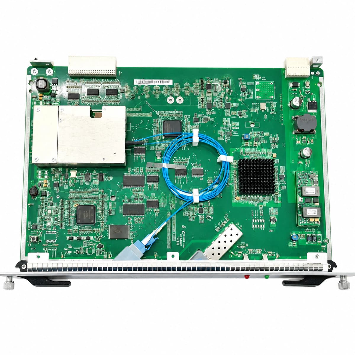
The Huawei SSEM4LWC1T01 is a high-performance optical line processing card engineered for Huawei OptiX OSN optical transport network platforms, delivering long-haul optical-electrical-optical conversion, dispersion compensation, and line-rate signal regeneration.

Equipment information

Brand
Huawei
Equipment model
Huawei SSEM4LWC1T01 Optical Board
Equipment type
SFP optical transceivers
Controller / software version
Confirm against the installed equipment
View full product specifications
Huawei SSEM4LWC1T01 Optical Board Official Product View 4

Information below comes from the current product catalogue. Confirm the controller, software version and configuration of the installed equipment separately.

Board Type
Long-haul wavelength-division multiplexing and optical signal processing transmission service board
Port Density & Specs
High-sensitivity narrow-linewidth laser transceiver interface
Supported Chassis
Huawei OptiX OSN 1800 / 3800 / 6800 / 8800 series
Subscriber Capacity
Supports automatic laser control (ALC) and dispersion compensation scheduling
Typical Power Consumption
< 45 W
Operating Temperature
0°C ~ +45°C (telecom-grade equipment-room operating conditions)

Alarms & troubleshooting

R_LOS (Loss of Optical Receive Signal)
STAT LED solid red, PORT link LED off
Fiber break or disconnected optical patch cord, contaminated LC connector, remote transmitter disabled or damaged, or line attenuation exceeding receiver sensitivity threshold
1. Measure incoming optical power at the RX port using an optical power meter to confirm it falls within receiver dynamic range; 2. Clean the LC patch cord connectors and the optical bulkhead sleeve using fiber optic cleaning tools; 3. Verify remote laser status on the peer transceiver (ensure ALS is not suppressing transmission); 4. Test link attenuation with an OTDR to identify line breaks or macro-bends; 5. If RX power is verified within specifications, replace the faulty SSEM4LWC1T01 board.
LASER_BIAS_HIGH (Transmitter Laser Bias Current High)
STAT LED blinking yellow at 1Hz, SRV LED solid yellow
Semiconductor laser diode degradation in the transmitter module; the internal APC loop increases bias current to sustain target launch power, reaching end-of-life threshold
1. Check the optical port DDM data via NCE/U2000 to review real-time laser bias current and performance historical trends; 2. Verify whether TX launch power is dropping below specifications; 3. Check board operating temperature to rule out excessive thermal compensation; 4. Schedule a maintenance window and replace the degraded SSEM4LWC1T01 board to prevent hard traffic outage.
IN_PWR_LOW (Input Optical Power Low)
STAT LED solid green, SRV LED solid yellow
High insertion loss due to macro-bending/stress on fiber, contaminated flange adapter, excessive fixed optical attenuator value, or degraded launch power from remote transmitter
1. Inspect optical jumpers in the ODF and cable trays for micro/macro-bending and relieve excessive cable tie tension; 2. Check and recalibrate/downsize any in-line fixed or variable optical attenuators (VOA); 3. Clean both connector end-faces and adapter sleeve using lint-free cassette cleaners and inspect with a fiberscope; 4. Query the remote node's TX optical power via NMS to verify transmit health; 5. If input signal from the line is certified compliant, execute local optical loopback to test the onboard receiver.
TEMP_OVER (Board / Optical Module Over-Temperature)
STAT LED solid or blinking red, subrack fans operating at full speed
Telecom room HVAC failure causing excessive ambient temperature, subrack air filter clogged with dust, fan tray assembly failure or stopped fans, or thermal accumulation from adjacent high-power boards
1. Verify telecom room HVAC operation and ensure ambient inlet temperature is within +15°C to +35°C; 2. Check the subrack FAN tray status and fan speed via NMS; replace failed fan tray immediately; 3. Clean or replace the chassis dust filter to restore unobstructed cooling airflow; 4. Ensure dummy plates are inserted in all empty slots and guide plates are installed correctly to maintain air pressure; 5. If cooling is restored but onboard temperature sensors report >85°C continuously, replace the SSEM4LWC1T01 board.
B1_EXC (B1 Excessive Bit Error Rate)
STAT LED solid green, SRV LED blinking yellow at 2Hz
Optical power operating at the marginal edge of receiver sensitivity or overload point causing low OSNR, dispersion compensation mismatch, optical return loss/reflection at poor connector joints, or clock and data recovery (CDR) jitter unlock
1. Query historical performance and current optical power in NMS to ensure RX power sits in the optimal dynamic window (typically >= 3dB above sensitivity and <= 5dB below overload); 2. Check optical return loss (ORL) with an OTDR to identify reflection events, clean or re-splice degraded splices/connectors; 3. Verify dispersion compensation modules (DCM) on the link to correct accumulated chromatic dispersion; 4. Check system clock synchronization references to eliminate upstream frequency jitter; 5. If the optical link parameters are nominal but B1 errors persist, replace the SSEM4LWC1T01 board.

Access Complete Maintenance & Full Alarm Troubleshooting Manual

This page lists high-frequency critical alarm codes commonly encountered in field maintenance. Comprehensive manufacturer troubleshooting matrices, board-level repair guides, detailed electrical schematics, and firmware commissioning manuals are delivered alongside equipment upon formal project procurement, accompanied by dedicated FAE technical support.

Share on-site information

  1. 01

    Identify the exact model

    Record the nameplate, system model and controller or module model.

  2. 02

    Keep the alarm details

    Record the full alarm text, indicator colour, timing and whether it persists.

  3. 03

    Describe recent changes

    Note recent replacements, software updates or configuration changes.

Record information visible in the existing interface. Electrical measurements, disassembly and replacement should follow the applicable manufacturer's manual and be performed by qualified personnel.

Your model and these details will be added to the enquiry form for you to review before sending.

Related technical articles

Browse the technical guides or send a question about this model.

View all articles

Need a replacement module or supporting equipment?

Confirm the full model, system configuration and compatibility requirements before enquiring about suitable products.

Ask about suitable products

Have a model and an on-site issue?

Share the exact model, alarm text and observed symptoms to help identify relevant information and compatibility requirements.

Request technical support