Huawei / SFP optical transceivers

Huawei H802A2EXL2 Uplink Board Equipment information & support

The Huawei H802A2EXL2 is a high-performance optical uplink interface line card engineered for Huawei SmartAX MA5680T and MA5683T central office chassis, delivering non-blocking upstream aggregation and carrier-grade protection switching toward metro IP backbones.

Equipment information

Brand
Huawei
Equipment model
Huawei H802A2EXL2 Uplink Board
Equipment type
SFP optical transceivers
Controller / software version
Confirm against the installed equipment
View full product specifications
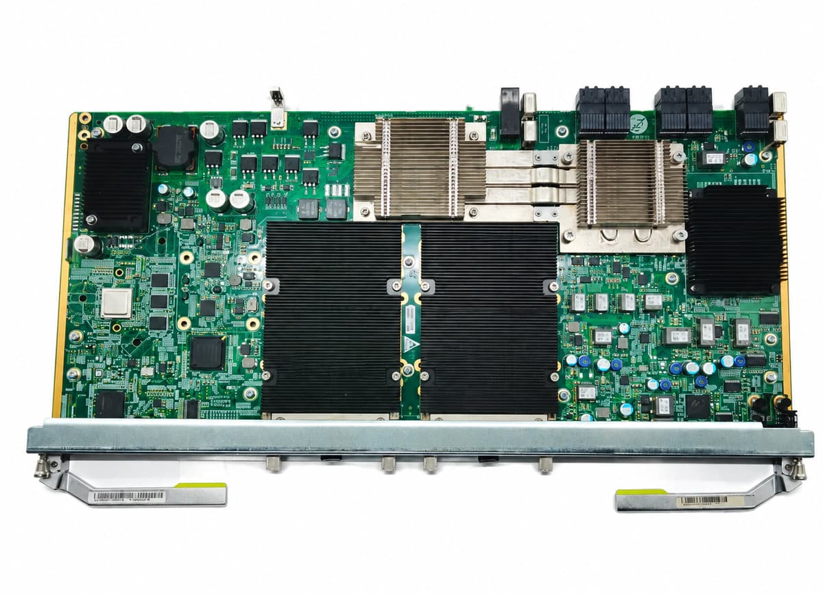
Huawei H802A2EXL2 Uplink Board Official Product View 4

Information below comes from the current product catalogue. Confirm the controller, software version and configuration of the installed equipment separately.

Board Type
High-speed uplink interface and switching cascade board
Port Density & Specs
High-capacity, high-speed optical-fiber uplink slot
Supported Chassis
Huawei SmartAX MA5680T / MA5683T
Subscriber Capacity
Supports dynamic link aggregation and millisecond-level protection switching
Typical Power Consumption
< 30 W
Operating Temperature
-40°C to +65°C

Alarms & troubleshooting

OPT_LOS (Optical RX Loss of Signal)
Port ACT/LINK LED OFF; RUN/ALM LED solid RED
Fiber patch cord disconnected, severed, or severely bent; peer uplink port laser disabled; faulty SFP+/XFP transceiver on H802A2EXL2, or optical RX power below sensitivity threshold
1. Verify optical patch cord connection, ensuring clean connectors and bend radius within limits. 2. Measure incoming optical power with an optical power meter to confirm it falls within receiver specs. 3. Run 'display port ddm-info' in CLI to inspect real-time RX optical power. 4. If peer TX is nominal but alarm persists, clean fiber end-faces or replace the optical transceiver on H802A2EXL2.
TX_BIAS_HIGH (Transmitter Laser Bias Current High)
RUN/ALM LED blinking or solid AMBER; Port ACT/LINK LED solid GREEN
Optical transmitter laser aging or degradation; local heat dissipation issue driving laser diode current up; improper supply voltage causing bias current to exceed threshold
1. Execute 'display port ddm-info' in OLT CLI to verify Bias Current value and threshold. 2. Inspect chassis fan tray status and dust filters to ensure sufficient airflow. 3. If bias current remains above threshold, proactively replace the optical module during maintenance window. 4. If the alarm persists with a new certified transceiver, investigate the H802A2EXL2 slot power delivery.
DDM_TEMP_HIGH (Transceiver DDM High Temperature Alarm)
RUN/ALM LED solid AMBER; Chassis FAN LED may illuminate RED
Equipment room ambient temperature exceeds operational limits (0°C to 55°C); chassis fan tray failure or clogged air filters; adjacent high-power boards obstructing cooling airflow
1. Check equipment room HVAC system to ensure ambient intake air is between 20°C and 25°C. 2. Run 'display fan' command to check fan speeds; replace faulty fan units or clean dusty air filters. 3. Run 'display port ddm-info' to identify the specific overheating port. 4. If ambient cooling is normal but a single transceiver reports extreme temperature (>75°C), replace the defective module.
ETH_CRC_ERR (Ethernet Port CRC Error Rate Exceeded)
Port ACT/LINK LED rapidly flashing GREEN; RUN/ALM LED green or flashing AMBER
Contaminated optical connector end-face causing dispersion and frame errors; clock synchronization or dispersion issue with peer switch/router; marginal optical power leading to degraded SNR
1. Run 'display port statistics' to monitor the increment rate of CRC and FCS error frames. 2. Inspect and clean optical connectors and transceiver sleeve using specialized fiber cleaning tools. 3. Run 'display port ddm-info' to verify RX optical power is safely above sensitivity threshold. 4. If errors continue to increment, replace the fiber patch cord, then replace the SFP+/XFP transceiver on H802A2EXL2.
BD_STATUS_ERR (Board Status Error / Hardware Fault)
RUN/ALM LED solid RED or completely OFF; Control board fails to communicate with board
H802A2EXL2 not fully seated in subrack backplane slot; onboard DC-DC power conversion module failure; CPLD/PHY self-test failure or backplane bus communication fault
1. Run 'display board 0' in CLI to check if the board status reports 'Failed' or 'Offline'. 2. Loosen ejector levers, re-seat the H802A2EXL2 board, and inspect backplane pins for physical damage. 3. Reinsert the board firmly along guide rails, close latches completely, and tighten faceplate screws. 4. If initialization fails, test the board in an alternate uplink slot; if fault persists, replace the H802A2EXL2 board.

Access Complete Maintenance & Full Alarm Troubleshooting Manual

This page lists high-frequency critical alarm codes commonly encountered in field maintenance. Comprehensive manufacturer troubleshooting matrices, board-level repair guides, detailed electrical schematics, and firmware commissioning manuals are delivered alongside equipment upon formal project procurement, accompanied by dedicated FAE technical support.

Share on-site information

  1. 01

    Identify the exact model

    Record the nameplate, system model and controller or module model.

  2. 02

    Keep the alarm details

    Record the full alarm text, indicator colour, timing and whether it persists.

  3. 03

    Describe recent changes

    Note recent replacements, software updates or configuration changes.

Record information visible in the existing interface. Electrical measurements, disassembly and replacement should follow the applicable manufacturer's manual and be performed by qualified personnel.

Your model and these details will be added to the enquiry form for you to review before sending.

Related technical articles

Browse the technical guides or send a question about this model.

View all articles

Need a replacement module or supporting equipment?

Confirm the full model, system configuration and compatibility requirements before enquiring about suitable products.

Ask about suitable products

Have a model and an on-site issue?

Share the exact model, alarm text and observed symptoms to help identify relevant information and compatibility requirements.

Request technical support