Huawei / SFP optical transceivers

Huawei H802A2EF2 Fast Ethernet Board Equipment information & support

The Huawei H802A2EF2 is a carrier-grade Fast Ethernet optical interface line card designed for Huawei SmartAX OLT chassis, delivering deterministic low-latency point-to-point fiber access and IEEE 802.3ah OAM telemetry for mission-critical industrial networks.

Equipment information

Brand
Huawei
Equipment model
Huawei H802A2EF2 Fast Ethernet Board
Equipment type
SFP optical transceivers
Controller / software version
Confirm against the installed equipment
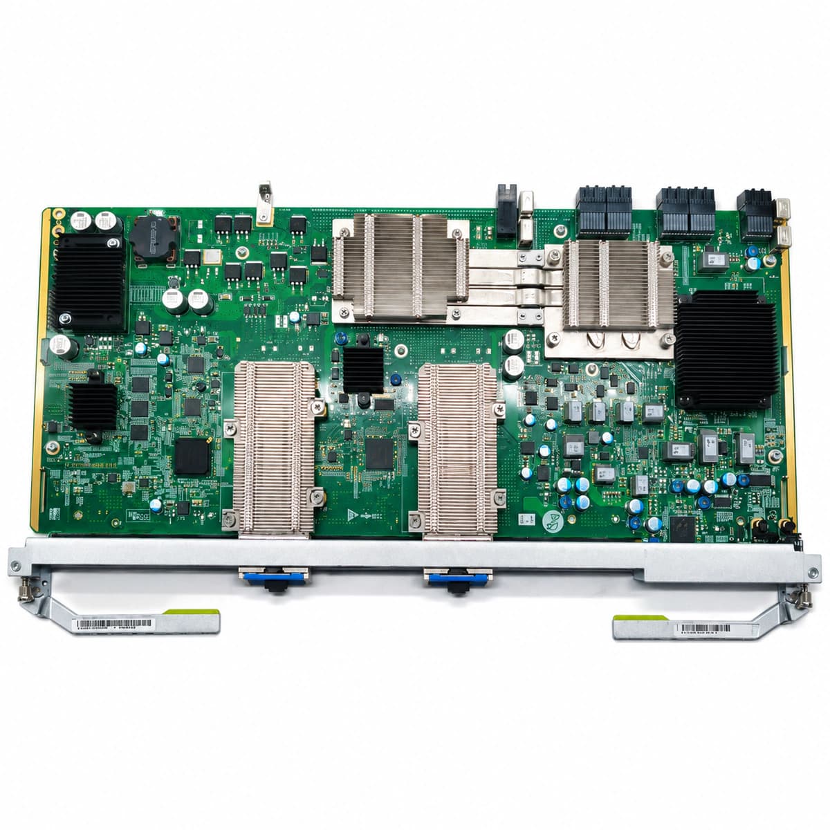
View full product specifications
Huawei H802A2EF2 Fast Ethernet Board Official Product View 5

Information below comes from the current product catalogue. Confirm the controller, software version and configuration of the installed equipment separately.

Board Type
Dedicated service access board for Fast Ethernet over fiber
Port Density & Specs
Multiple high-density 100-megabit fiber-optic SFP interfaces
Supported Chassis
Huawei SmartAX MA5680T / MA5683T / MA5608T
Subscriber Capacity
Supports IEEE 802.3ah / 802.1ag carrier-grade Ethernet OAM for rapid fault isolation
Typical Power Consumption
< 30 W
Operating Temperature
-40°C to +65°C

Alarms & troubleshooting

ETH_LOS (Ethernet Optical Loss of Signal)
Board ALM LED solid red, corresponding port LINK/ACT LED off
Broken or severely bent optical fiber; peer transmitter disabled or faulty; faulty or poorly seated SFP transceiver RX; heavily contaminated optical connector ferrule.
1. Verify physical fiber cabling between H802A2EF2 port and peer equipment, ensuring secure latching. 2. Measure RX optical power with an optical power meter to confirm it meets SFP sensitivity specifications. 3. Clean optical fiber connectors and adapter sleeves with specialized cleaning tools. 4. Check peer port laser emission status and intermediate ODF/patching if RX power is absent. 5. Replace the SFP transceiver on the affected port if optical power is normal but LOS persists.
OPT_BIAS_OVER (Optical Laser Bias Current High)
Board ALM LED solid yellow, corresponding port LINK/ACT LED blinking green
Internal laser diode degradation over aging causing auto-bias current saturation; defective transceiver internal circuitry or failed internal thermal control.
1. Run 'display optical-module info' via CLI to query bias current values and alarm thresholds. 2. Ensure board operating temperature is within rated environmental specifications. 3. Schedule a maintenance window and prepare an approved replacement FE SFP module matching wavelength and reach. 4. Replace the degraded SFP module and verify DDM parameters normalize via CLI. 5. Confirm that the alarm automatically clears.
OPT_TEMP_HIGH (Optical Module High Temperature Alarm)
Board ALM LED solid yellow, subrack FAN tray runs at maximum speed with increased acoustic noise
Air conditioning failure in equipment room; subrack air filter clogged by heavy dust; fan tray failure or fan speed control fault; internal short/thermal anomaly inside SFP.
1. Inspect room air conditioning to restore ambient temperature below 40°C. 2. Remove the subrack air filter, clean accumulated dust, or replace the filter element. 3. Execute 'display fan' to check fan tray operational status; replace fan tray immediately if fans stalled. 4. If only a single SFP module reports excessive temperature while adjacent ports are normal, replace that specific SFP. 5. Verify that temperature metrics return below warning threshold and alarm clears.
CRC_ERR_OVER (Port CRC Error Packets Over Threshold)
Board ALM LED off or slow-flashing yellow, corresponding port LINK/ACT LED blinking fast and irregularly
Optical RX power hovering near receiver sensitivity threshold due to microbends; contaminated or scratched fiber connector ferrule; severe electromagnetic interference; degraded SFP photodiode causing excessive jitter.
1. Run 'display port statistics <port-id>' in CLI to track the rate of CRC and frame check error accumulation. 2. Confirm RX optical power via DDM is well above sensitivity threshold (at least 3 dB margin). 3. Inspect patch cord ferrules with a fiber scope; clean or replace scratched/damaged patch cords. 4. Verify optical patch cords and subracks are separated from high-voltage power conduits and VFD inverters. 5. If CRC errors continue to increase, swap the FE SFP transceiver and clear port statistics to verify stability.
ETH_LINK_DOWN (Ethernet Port Auto-Negotiation Failure / Link Down)
Board ALM LED red or yellow, corresponding port LINK/ACT LED completely off
Speed/duplex mode mismatch between ports (e.g., forced 100M Full-Duplex on one side vs auto-negotiation on the other); incompatible transceiver type (e.g., 100Base-FX vs 1000Base-X); port manually disabled via administrative shutdown.
1. Run 'display interface <port-id>' to inspect the administrative status, current speed, and negotiation state. 2. If the interface is administratively disabled, enter interface configuration mode and execute 'undo shutdown'. 3. Align speed/duplex settings on both sides: force both to 100M full duplex ('speed 100', 'duplex full', 'undo negotiation auto') or enable auto-negotiation on both ends. 4. Verify SFP part numbers on both ends to ensure compatible Fast Ethernet optical transceivers (matched wavelength, BiDi vs dual-fiber). 5. Confirm that port LINK/ACT LED returns to solid green and blinks during packet forwarding.

Access Complete Maintenance & Full Alarm Troubleshooting Manual

This page lists high-frequency critical alarm codes commonly encountered in field maintenance. Comprehensive manufacturer troubleshooting matrices, board-level repair guides, detailed electrical schematics, and firmware commissioning manuals are delivered alongside equipment upon formal project procurement, accompanied by dedicated FAE technical support.

Share on-site information

  1. 01

    Identify the exact model

    Record the nameplate, system model and controller or module model.

  2. 02

    Keep the alarm details

    Record the full alarm text, indicator colour, timing and whether it persists.

  3. 03

    Describe recent changes

    Note recent replacements, software updates or configuration changes.

Record information visible in the existing interface. Electrical measurements, disassembly and replacement should follow the applicable manufacturer's manual and be performed by qualified personnel.

Your model and these details will be added to the enquiry form for you to review before sending.

Related technical articles

Browse the technical guides or send a question about this model.

View all articles

Need a replacement module or supporting equipment?

Confirm the full model, system configuration and compatibility requirements before enquiring about suitable products.

Ask about suitable products

Have a model and an on-site issue?

Share the exact model, alarm text and observed symptoms to help identify relevant information and compatibility requirements.

Request technical support