Huawei / Indoor power systems

Huawei ETP48400-C4A1 Equipment information & support

Huawei ETP48400-C4A1 is an industrial-grade 9U 19-inch rack-mounted embedded DC power system engineered for high-capacity telecom sites and IT equipment rooms, delivering up to 400A (-48V DC) continuous output across 8 rectifier slots with three-phase/single-phase flexible AC input and intelligent SMU02C monitoring.

Equipment information

Brand
Huawei
Equipment model
Huawei ETP48400-C4A1
Equipment type
Indoor power systems
Controller / software version
Confirm against the installed equipment
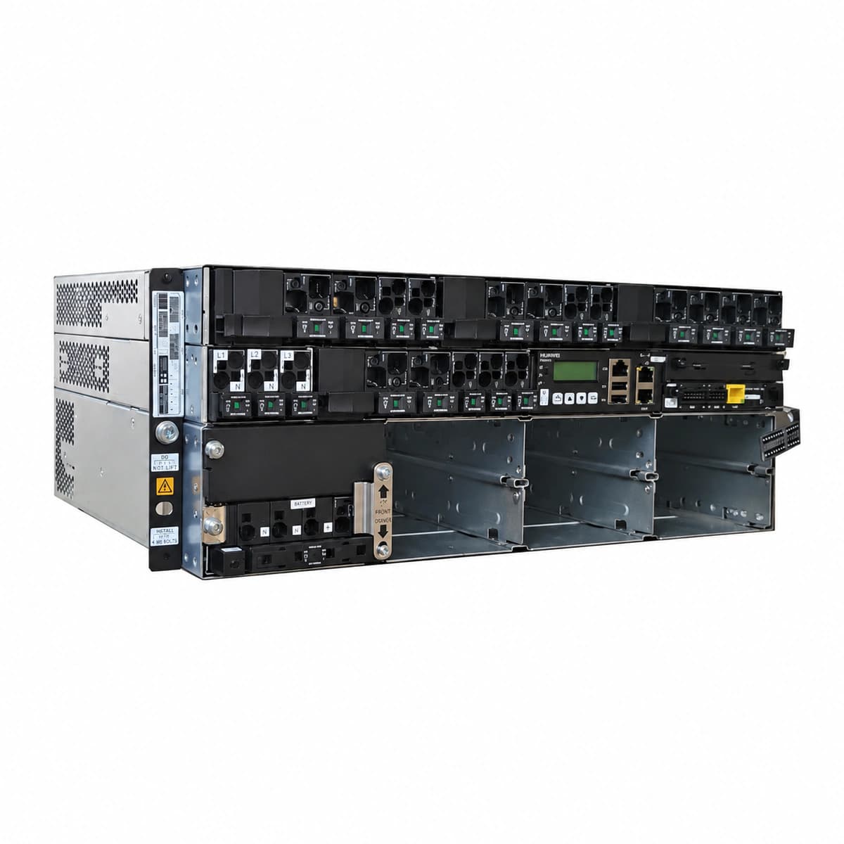
View full product specifications
Huawei ETP48400-C4A1 9U 400A Embedded Telecom DC Power Subrack System (with SMU02C & R4850 Compatibility) Official Studio Photo 1

Information below comes from the current product catalogue. Confirm the controller, software version and configuration of the installed equipment separately.

System Output Capacity
400A (-48V DC)
AC Input Voltage Range
85V AC ~ 300V AC (Supports 3-Phase / 1-Phase Input)
Physical Form Factor
9U 19-inch Standard Subrack Embedded Chassis
Rectifier Module Slots
8 Slots (Compatible with R4850G2 / R4850N1 50A Rectifiers)
System Monitoring Controller
SMU02C Intelligent Network Management Controller
Power Conversion Efficiency
≥ 96% (Ultra-High Frequency Efficiency)

Alarms & troubleshooting

AC_FAIL (AC Input Failure)
SMU ALM LED steady red; Rectifier green RUN LED off
Utility grid blackout, AC input circuit breaker tripped, or input phase loss/voltage drop below 85 VAC
1. Measure voltage across AC input terminals (L1/L2/L3 to N) with a digital multimeter. 2. Verify whether upstream mains switches and internal AC input breakers are switched on. 3. If grid power is normal, inspect AC contactor condition and surge protection circuit breakers, then restore power.
RECT_HVSD (Rectifier Output Overvoltage Lockout)
Faulty rectifier red ALM LED steady on; yellow LED off
Internal PWM loop regulation failure causing DC output to exceed HW protection threshold (typically 59.5V), triggering latch-off
1. Identify the faulty rectifier with red ALM LED and disengage it from the shelf backplane. 2. Wait 60 seconds for internal bus capacitors to discharge, then reinsert firmly. 3. If the red alarm persists after repowering, declare hardware component failure and replace the rectifier.
DC_LOW_VOLT_LLVD (DC Bus Undervoltage & LLVD Disconnect)
SMU ALM LED steady red, buzzer sounds continuously, LLVD trip status active
Prolonged mains outage discharging batteries below LLVD trip threshold (default 45V/47V), or total rectifier group outage
1. Connect emergency diesel generator to restore AC mains immediately. 2. Observe SMU until bus voltage rises above reconnect threshold and verify LLVD contactor automatically picks up. 3. If contactor fails to close automatically, execute manual LLVD close command via SMU display menu.
RECT_COMM_FAIL (Rectifier Communication Failure)
SMU ALM LED yellow; affected rectifier yellow LED blinks at 0.5Hz
Internal CAN bus communication pin bent/oxidized, backplane edge-connector loose contact, or rectifier address ID conflict
1. Unseat the communication-lost rectifier and inspect rear interface pins for debris or mechanical bending. 2. Re-seat and secure latch handle firmly, checking if SMU acknowledges the module. 3. Swap the unit into an adjacent empty slot; if failure follows module, replace rectifier; if fault stays on slot, replace subrack backplane.
SPD_FAIL (AC Surge Protective Device Fault)
SMU ALM LED yellow; SPD mechanical flag turned from green to red, or SPD circuit breaker open
AC mains lightning strike or high transient surge degraded the metal oxide varistors (MOV), tripping the dry-contact signaling microswitch
1. Inspect the SPD window indicators to locate the failed cartridge displaying red. 2. Switch off the dedicated SPD backup circuit breaker. 3. Pull out the defective pluggable MOV cartridge, install a matching replacement module (e.g., Class C/40kA), re-engage the breaker, and clear the alarm on SMU.

Access Complete Maintenance & Full Alarm Troubleshooting Manual

This page lists high-frequency critical alarm codes commonly encountered in field maintenance. Comprehensive manufacturer troubleshooting matrices, board-level repair guides, detailed electrical schematics, and firmware commissioning manuals are delivered alongside equipment upon formal project procurement, accompanied by dedicated FAE technical support.

Share on-site information

  1. 01

    Identify the exact model

    Record the nameplate, system model and controller or module model.

  2. 02

    Keep the alarm details

    Record the full alarm text, indicator colour, timing and whether it persists.

  3. 03

    Describe recent changes

    Note recent replacements, software updates or configuration changes.

Record information visible in the existing interface. Electrical measurements, disassembly and replacement should follow the applicable manufacturer's manual and be performed by qualified personnel.

Your model and these details will be added to the enquiry form for you to review before sending.

Related technical articles

Browse the technical guides or send a question about this model.

View all articles

Need a replacement module or supporting equipment?

Confirm the full model, system configuration and compatibility requirements before enquiring about suitable products.

Ask about suitable products

Have a model and an on-site issue?

Share the exact model, alarm text and observed symptoms to help identify relevant information and compatibility requirements.

Request technical support