Huawei / Indoor power systems

Huawei ETP48200-C2A6 Equipment information & support

The Huawei ETP48200-C2A6 is an industrial-grade, ultra-compact 2U 19-inch rack-mounted embedded DC power subrack designed for telecommunication base stations, microwave repeater sites, and optical transmission hubs. Engineered with a wide 85V AC to 300V AC operating range and four 50A rectifier slots, it delivers a regulated -48V DC output up to 200A capacity, managed intelligently via the SMU02C controller with multi-stage battery disconnect protections.

Equipment information

Brand
Huawei
Equipment model
Huawei ETP48200-C2A6
Equipment type
Indoor power systems
Controller / software version
Confirm against the installed equipment
View full product specifications
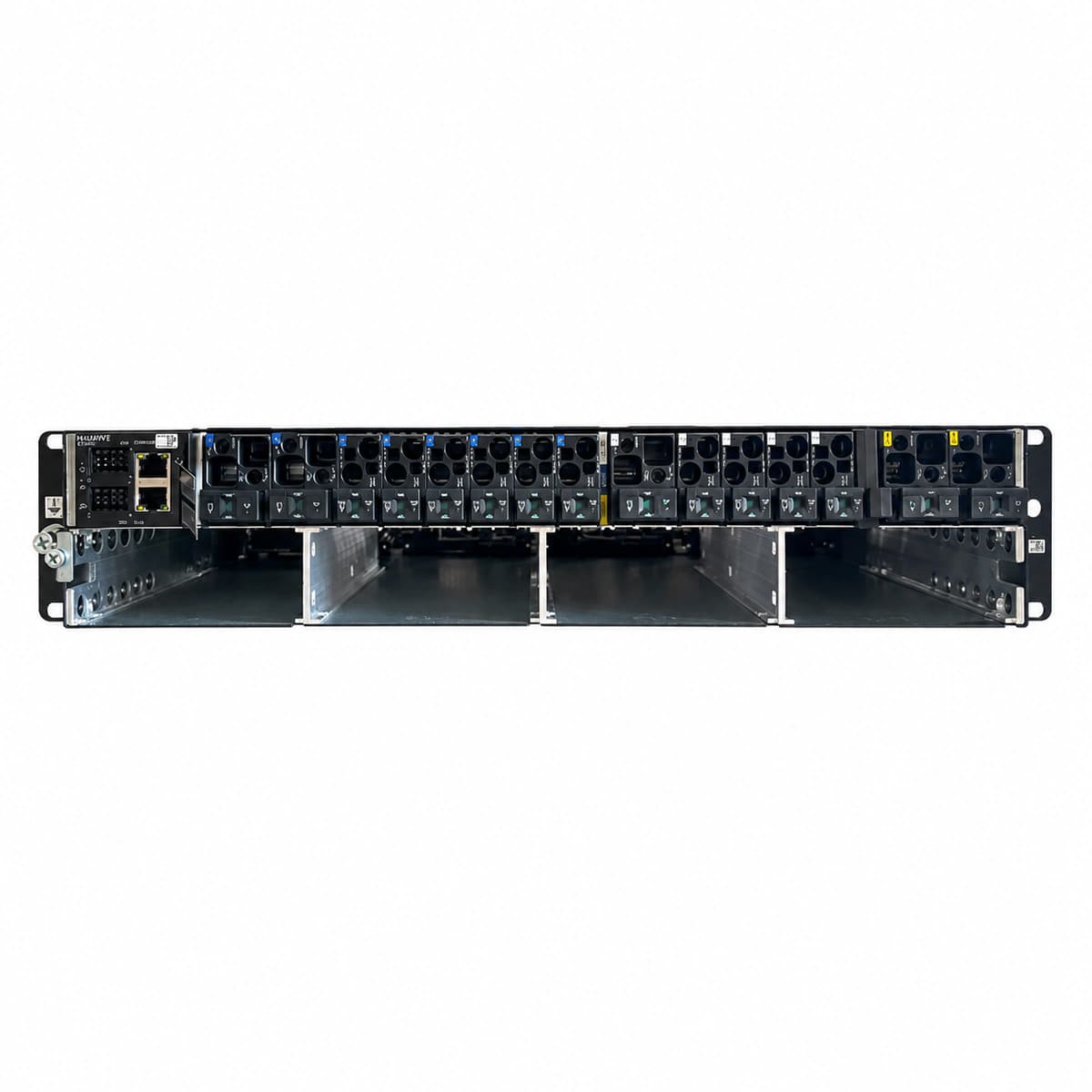
Huawei ETP48200-C2A6 2U 200A Embedded DC Power System (with SMU02C Controller) Official Studio Photo 3

Information below comes from the current product catalogue. Confirm the controller, software version and configuration of the installed equipment separately.

System Output Capacity
200A (-48V DC)
AC Input Voltage Range
85V AC ~ 300V AC (Nominal 220/380V AC)
Physical Form Factor
2U 19-inch Standard Compact Subrack Chassis
Rectifier Module Slots
4 Slots (Compatible with R4850G2 / R4850N1 50A Rectifiers)
System Monitoring Controller
SMU02C Intelligent Network Controller Unit
Power Conversion Efficiency
≥ 96% (Ultra-High Efficiency Conversion)

Alarms & troubleshooting

AC_FAIL (AC Power Failure / Under-Voltage)
SMU ALM LED steady red, RUN LED steady green; Rectifier green LED off, yellow LED flashing or off
Mains grid outage, upstream or chassis AC input circuit breaker tripped, or loose terminal wiring causing input voltage to drop below 85 V AC
1. Measure phase-neutral / phase-phase voltage at ETP48200 AC input terminals with a multimeter to verify grid availability. 2. Inspect the upstream distribution breaker and chassis AC input switch (MCB) for tripping, then reset. 3. Verify and tighten all AC input terminal screw connections. 4. If the breaker trips immediately upon closure, check the SPD module and internal wiring for short circuits or earth faults.
REC_HVSD (Rectifier Hardware Overvoltage Shutdown)
Faulty rectifier red FAULT LED steady on; SMU red ALM LED on, LCD displays 'Rectifier Fault'
Internal PWM loop breakdown, feedback loop open-circuit, or voltage sensing failure causing output to exceed hardware threshold (58.5V–60V DC)
1. Identify the slot number of the triggered rectifier module using the SMU display or WebUI. 2. Unlock the module latch, slide it out of the subrack to disconnect from the backplane, and wait 3 minutes for bus capacitors to discharge. 3. Re-insert the module firmly into the slot and close the locking handle. 4. If the red indicator stays latched after reboot, internal hardware is damaged; replace with a spare rectifier module (e.g., R4850G/R4850N).
BLVD_ACTIVE (Battery Low Voltage Disconnect Active)
SMU red ALM LED on with continuous buzzer; BLVD DC contactor mechanically open; bus voltage drops below threshold (default 43.2 V DC)
Prolonged mains blackout without generator start causing batteries to deplete to cutoff limit; or total rectifier failure with blown battery fuse or damaged contactor driver
1. Connect a mobile emergency generator or external power vehicle to restore AC input to rectifiers immediately. 2. Inspect battery circuit breakers and fuses; measure individual block voltages to check for cell reversal or damage. 3. Verify that BLVD and LLVD cutoff thresholds in the SMU configuration match engineering battery specifications. 4. Once AC power is restored, rectifiers automatically resume operation, contactor re-closes, and SMU initiates equalized/boost charging.
FAN_FAULT (Rectifier Fan Blocked / Speed Abnormal)
Rectifier yellow LED steady on, SMU yellow ALM LED on, LCD displays 'Rectifier Fan Alarm', rectifier operates in derated power mode
Severe dust accumulation in the rectifier airflow channel, foreign objects physically seizing fan blades, worn motor bearings, or open Hall sensor circuit
1. Remove the air filter on the subrack and clean the rectifier intake vents and fan mesh using an ESD brush and compressed air. 2. Extract the alarmed rectifier module, use an insulated probe to spin the blades, and check for physical seizure or entangled debris. 3. Re-seat and latch the module; verify if the fan ramps to full speed during the initial power-on self-test (POST). 4. If the fan does not spin or the speed alarm persists, replace the internal fan assembly or swap the entire rectifier module.
CAN_COMM_FAIL (Rectifier to SMU CAN Bus Communication Failure)
Rectifier green RUN LED flashes slowly (0.5 Hz), SMU yellow ALM LED on, LCD shows 'Module Comm Fail' or offline; rectifier operates in autonomous mode
Oxidized or bent CAN bus pins on the subrack backplane, poor contact on the slot gold fingers, open termination resistor (120 ohms), or defective CAN transceiver IC
1. Reseat both the offline rectifier module and the SMU controller firmly into their respective slots to ensure solid backplane engagement. 2. Inspect the backplane gold fingers and multi-pin connectors; clean with contact cleaner spray and straighten any slightly bent pins. 3. Power down and measure resistance between CAN_H and CAN_L signal lines with a multimeter (nominal dual-termination value should be ~60 ohms). 4. Swap the affected rectifier into an adjacent working slot: if the fault follows the module, replace the rectifier; if it stays at the slot, replace the backplane or SMU.

Access Complete Maintenance & Full Alarm Troubleshooting Manual

This page lists high-frequency critical alarm codes commonly encountered in field maintenance. Comprehensive manufacturer troubleshooting matrices, board-level repair guides, detailed electrical schematics, and firmware commissioning manuals are delivered alongside equipment upon formal project procurement, accompanied by dedicated FAE technical support.

Share on-site information

  1. 01

    Identify the exact model

    Record the nameplate, system model and controller or module model.

  2. 02

    Keep the alarm details

    Record the full alarm text, indicator colour, timing and whether it persists.

  3. 03

    Describe recent changes

    Note recent replacements, software updates or configuration changes.

Record information visible in the existing interface. Electrical measurements, disassembly and replacement should follow the applicable manufacturer's manual and be performed by qualified personnel.

Your model and these details will be added to the enquiry form for you to review before sending.

Related technical articles

Browse the technical guides or send a question about this model.

View all articles

Need a replacement module or supporting equipment?

Confirm the full model, system configuration and compatibility requirements before enquiring about suitable products.

Ask about suitable products

Have a model and an on-site issue?

Share the exact model, alarm text and observed symptoms to help identify relevant information and compatibility requirements.

Request technical support