Huawei / Power management

ETP48600-C11A1 Equipment information & support

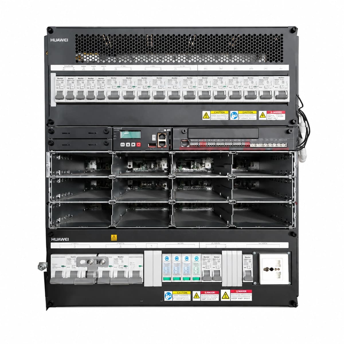
The ETP48600-C11A1 is an 11U subrack -48VDC embedded telecom power system delivering up to 600A rated output, accommodating up to eight high-efficiency rectifiers and a smart monitoring controller.

Equipment information

Brand
Huawei
Equipment model
ETP48600-C11A1
Equipment type
Power management
Controller / software version
Confirm against the installed equipment
View full product specifications
Huawei ETP48600-C11A1 Official White Background Photo View 1

Information below comes from the current product catalogue. Confirm the controller, software version and configuration of the installed equipment separately.

Smart Monitoring Controller
SMU02C Central Network Controller Unit
AC Input Voltage Range
85VAC ~ 300VAC (3-Phase 380V / 220V Dual Source) VAC
Cooling Method
Zoned front-to-rear air cooling
Nominal Output Voltage
-48VDC VDC
Managed Rectifier Capacity
12 × 50A (Supports R4850G2 / R4850N2 Modules)
Rated Output Current
600A (System Capacity 34.8kW)

Alarms & troubleshooting

AC_FAIL
SMU ALM LED steady red, RUN LED blinking green; rectifier AC input LEDs OFF/red
Upstream AC mains blackout, input circuit breaker (MCB) trip, contactor failure, or AC input phase voltage dropping below 80VAC cutoff.
1. Measure upstream phase-to-neutral voltages with a true-RMS DMM; 2. Check input MCB toggle status and reset if tripped after verifying no short circuit; 3. Inspect AC surge protective device (SPD) cartridges for thermal puncture or shorting; 4. Verify SMU AC voltage sampling terminal integrity.
BATT_DISCONNECT
SMU ALM LED blinking red, buzzer intermittent; PDU battery status indicators OFF
Battery bank circuit breaker manually open or tripped, Hall current sensor disconnected, or DC battery fuse blown.
1. Inspect battery MCB/MCCB positions and auxiliary contact wiring; 2. Measure DC voltage across battery fuses; a voltage drop >1V indicates a blown fuse requiring replacement; 3. Verify Hall-effect sensor cable seating; 4. Measure open-circuit voltage across battery bank string.
BLVD_ACTION
SMU ALM LED steady red; main DC load bus de-energized, payload dropped
Extended AC outage causing battery depletion to final cutoff (default 43.2VDC), tripping BLVD contactor; or failed bus voltage sensor.
1. Deploy mobile generator to restore AC input; 2. Measure actual battery terminal voltage; if below 43V, do not bypass manually—allow rectifiers to recover batteries; 3. If AC is normal and contactor tripped erroneously, inspect the SMU relay driver and replace the control sub-board.
RECT_FAULT
Faulty rectifier module LED steady red or blinking yellow, green power LED OFF; SMU ALM ON
Internal PFC stage failure, DC/DC converter thermal shutdown, locked cooling fan rotor, or hardware output overvoltage latch.
1. Check if the module fan is obstructed; clear dust filters; 2. Withdraw module and inspect backplane gold fingers for electrical arcing; 3. Swap the module to an unpopulated slot to rule out slot-specific pin faults; 4. If red fault LED persists, hot-swap with a healthy unit.
BATT_TEMP_HIGH
SMU ALM LED steady yellow, LCD display scrolling high-temperature warning
Battery compartment HVAC failure, ambient room temperature exceeding preset threshold (default 50°C), internal cell short circuit causing thermal runaway, or drifted NTC probe.
1. Check site HVAC cooling operation and reset AC units; 2. Scan battery blocks with an infrared thermal imager to identify overheated cells (>55°C) and isolate them; 3. Cross-reference NTC readings with a calibrated digital thermometer; replace probe if error >3°C; 4. Temporarily restrict rectifier recharge current limit via SMU.

Access Complete Maintenance & Full Alarm Troubleshooting Manual

This page lists high-frequency critical alarm codes commonly encountered in field maintenance. Comprehensive manufacturer troubleshooting matrices, board-level repair guides, detailed electrical schematics, and firmware commissioning manuals are delivered alongside equipment upon formal project procurement, accompanied by dedicated FAE technical support.

Share on-site information

  1. 01

    Identify the exact model

    Record the nameplate, system model and controller or module model.

  2. 02

    Keep the alarm details

    Record the full alarm text, indicator colour, timing and whether it persists.

  3. 03

    Describe recent changes

    Note recent replacements, software updates or configuration changes.

Record information visible in the existing interface. Electrical measurements, disassembly and replacement should follow the applicable manufacturer's manual and be performed by qualified personnel.

Your model and these details will be added to the enquiry form for you to review before sending.

Related technical articles

Browse the technical guides or send a question about this model.

View all articles

Need a replacement module or supporting equipment?

Confirm the full model, system configuration and compatibility requirements before enquiring about suitable products.

Ask about suitable products

Have a model and an on-site issue?

Share the exact model, alarm text and observed symptoms to help identify relevant information and compatibility requirements.

Request technical support