Huawei / Power management

ETP48200-C5B7002 Equipment information & support

The ETP48200-C5B7002 is a 5U carrier-grade embedded AC/DC rectifier power system delivering up to 200A nominal output at -48VDC, controlled by the SMU02C monitoring unit and supporting hot-swappable high-efficiency rectifiers.

Equipment information

Brand
Huawei
Equipment model
ETP48200-C5B7002
Equipment type
Power management
Controller / software version
Confirm against the installed equipment
View full product specifications
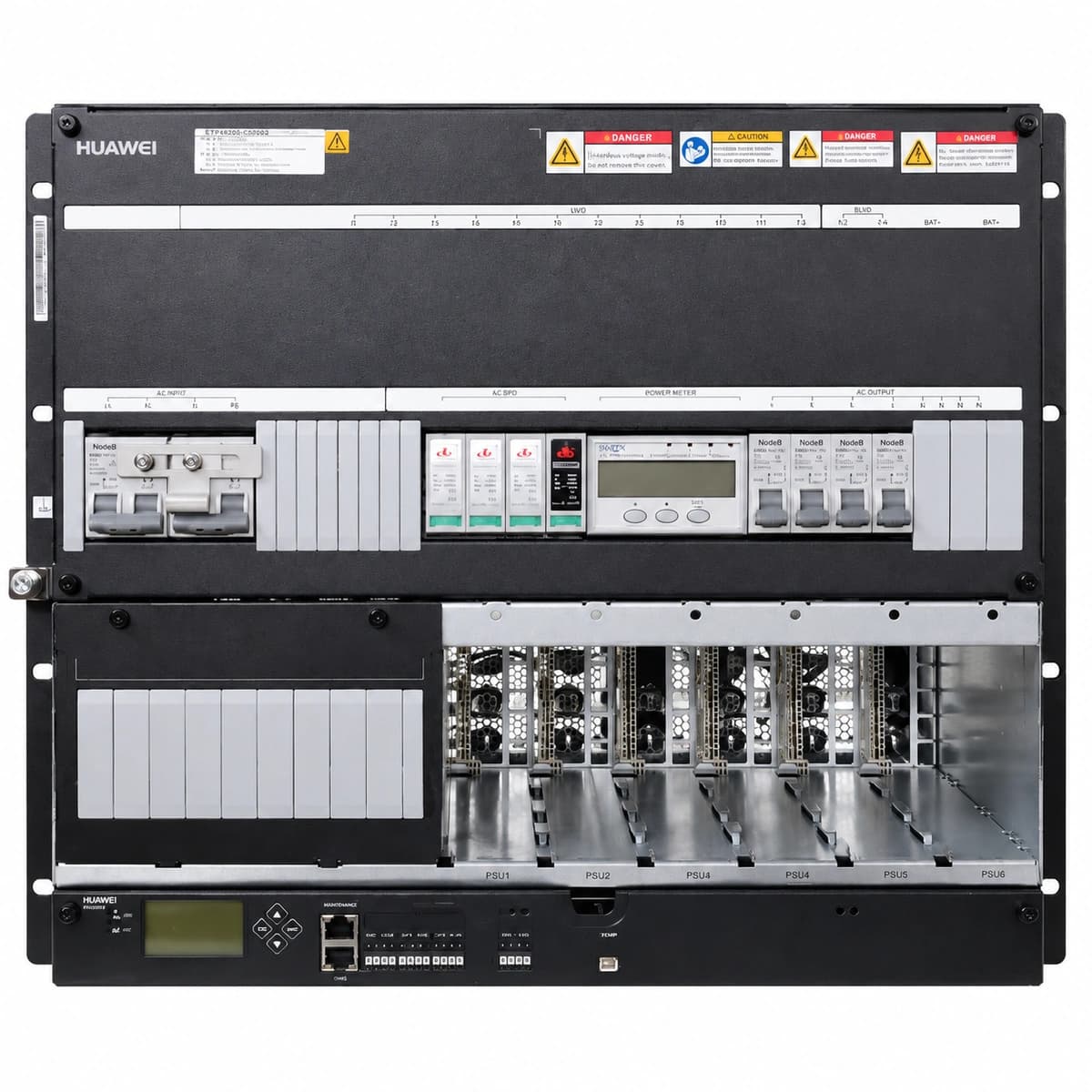
Huawei ETP48200-C5B7002 Official White Background Photo View 1

Information below comes from the current product catalogue. Confirm the controller, software version and configuration of the installed equipment separately.

AC Input Voltage Range
85VAC ~ 300VAC (1-Phase 220V / 3-Phase 380V Compatible) VAC
Smart Monitoring Controller
SMU02B / SMU02C Smart Monitoring Unit
Cooling Method
Built-in speed-controlled fan cooling
Nominal Output Voltage
-48VDC VDC
Rated Output Current
200A (System Capacity 11.6kW)
Managed Rectifier Capacity
4 × 50A (Supports R4850G2 / R4850N1 Rectifiers)

Alarms & troubleshooting

AC_FAIL
Monitor ALM indicator solid red; rectifier AC run LED off, yellow alert LED on
Utility mains outage, AC upstream breaker tripping, or AC phase voltage below 80VAC threshold.
1. Measure incoming AC line-to-line and phase voltages with a multimeter to verify mains presence; 2. Check if the main AC breaker or surge protection breaker has tripped; 3. Verify physical wiring torque at terminal blocks; 4. If voltage is within 85-300VAC, reboot the SMU02C or replace the AC sensing unit.
DC_VOL_LOW
Monitor ALM indicator blinking red, audible buzzer active
Extended battery discharge following AC failure; bus voltage has fallen below the programmable low voltage threshold (-45.0VDC to -47.0VDC).
1. Deploy an emergency mobile diesel generator immediately to feed the AC input; 2. Verify whether the LLVD contactor has successfully disconnected non-critical loads to preserve remaining battery runtime; 3. Prepare critical network nodes for safe shutdown if BLVD threshold (-43.2VDC) is approaching.
RECT_FAIL
Rectifier Fault LED solid red, monitor displays rectifier failure alarm
Internal rectifier power hardware fault, output overvoltage lock-out, blocked internal cooling fan, or loose backplane pin seating.
1. Pull out the failed rectifier module, inspect the slot and gold-finger contacts, and re-seat firmly; 2. If the red fault LED persists, check whether the cooling fan is rotating or obstructed; 3. Query the SMU02C for the exact diagnostic subcode; 4. Hot-swap and replace the unit with a spare identical rectifier module.
BLVD_DISCONN
Monitor ALM indicator solid red, battery circuit physically isolated
Battery bank voltage reached the critical BLVD disconnect threshold (-43.2VDC), tripping the contactor to prevent cell destruction, or the contactor drive circuit failed.
1. Restore AC power; once rectifiers re-energize the DC bus above reconnection voltage (-48V ~ -50V), the BLVD contactor will auto-reclose; 2. Never bypass or manually force the contactor closed while grid is absent; 3. If bus voltage is normal but contactor stays open, verify SMU02C driver control terminals and the 48V auxiliary coil resistance.
BATT_TEMP_HIGH
Monitor ALM indicator solid yellow
Battery compartment HVAC failure, restricted ventilation airflow, or internal cell thermal runaway pushing temperatures beyond the safety threshold (typically +50°C).
1. Inspect site air conditioning and airflow louvers in the battery compartment; 2. Scan battery blocks with an infrared thermal imager to identify localized high-temperature or bulging monoblocs; 3. Isolate or replace any thermally compromised battery monobloc immediately; 4. Ensure temperature sensors are attached to the cell casing, not placed directly in hot air exhaust paths.

Access Complete Maintenance & Full Alarm Troubleshooting Manual

This page lists high-frequency critical alarm codes commonly encountered in field maintenance. Comprehensive manufacturer troubleshooting matrices, board-level repair guides, detailed electrical schematics, and firmware commissioning manuals are delivered alongside equipment upon formal project procurement, accompanied by dedicated FAE technical support.

Share on-site information

  1. 01

    Identify the exact model

    Record the nameplate, system model and controller or module model.

  2. 02

    Keep the alarm details

    Record the full alarm text, indicator colour, timing and whether it persists.

  3. 03

    Describe recent changes

    Note recent replacements, software updates or configuration changes.

Record information visible in the existing interface. Electrical measurements, disassembly and replacement should follow the applicable manufacturer's manual and be performed by qualified personnel.

Your model and these details will be added to the enquiry form for you to review before sending.

Related technical articles

Browse the technical guides or send a question about this model.

View all articles

Need a replacement module or supporting equipment?

Confirm the full model, system configuration and compatibility requirements before enquiring about suitable products.

Ask about suitable products

Have a model and an on-site issue?

Share the exact model, alarm text and observed symptoms to help identify relevant information and compatibility requirements.

Request technical support