Huawei / Indoor power systems

ETP48200-C5B7 Equipment information & support

Huawei ETP48200-C5B7 is a 5U standard embedded DC power system (200A) equipped with SMU02 LCD controller, 4 × 50A rectifier slots, and comprehensive surge protection.

Equipment information

Brand
Huawei
Equipment model
ETP48200-C5B7
Equipment type
Indoor power systems
Controller / software version
Confirm against the installed equipment
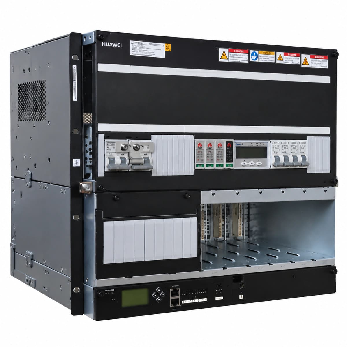
View full product specifications
ETP48200-C5B7 Official Product View 1

Information below comes from the current product catalogue. Confirm the controller, software version and configuration of the installed equipment separately.

AC Input Voltage Range
220V/380V compatible (85~300VAC) VAC
Nominal DC Output Voltage
-48 V DC
Rectifier Module Slots
4 × R4850G2 / R4850G6 (50A) Slots
Physical Dimensions Spec
222 (5U) × 442 × 360 mm
System Monitoring Controller
SMU02B / SMU02C intelligent monitoring unit

Alarms & troubleshooting

AC_FAIL (AC Mains Failure / Phase Loss)
SMU ALM indicator steady red; Rectifier RUN indicator OFF, ALM indicator steady red
Utility grid blackout, input AC circuit breaker tripped, AC phase voltage below 85 VAC, or AC phase loss
1. Measure phase and line voltages at the AC input terminal block using a multimeter. 2. Verify that the main AC input breaker and individual rectifier branch breakers are closed. 3. If grid power is normal, inspect the AC surge protection board and voltage detection cabling.
REC_HVSD (Rectifier Output Overvoltage Hardware Shutdown)
Faulty rectifier ALM indicator steady red, RUN indicator OFF; SMU reports Major Rectifier Alarm
Internal PWM loop failure, reference circuit breakdown causing DC bus voltage to exceed 59.5 VDC, or current-sharing runaway
1. Identify the slot location of the faulty module from the SMU alarm menu. 2. Pull the handle to unlock and extract the faulty rectifier module, wait 1 minute for internal discharge, then re-insert. 3. If the red ALM LED reappears immediately and the module remains locked, replace it with an operational R4850G2/R4850N2 module.
DC_LOW_VOLT (DC Bus Undervoltage / LLVD Disconnect)
SMU ALM indicator steady red, buzzer active, LLVD contactor disconnected status active
Prolonged AC power outage, battery string discharged below the undervoltage threshold (default 43.2–44.0 VDC), causing LLVD contactor trip
1. Connect an emergency generator to restore AC mains and confirm rectifiers power on to charge the DC bus. 2. Monitor the SMU screen to verify that the LLVD contactor automatically reconnects as DC voltage rises above 48 VDC. 3. If bus voltage recovers but the contactor remains open, perform a manual contactor test via SMU and verify the contactor control coils.
COMM_FAIL (Rectifier CAN Bus Communication Lost)
Rectifier RUN and ALM indicators flash alternately at 0.5 Hz; SMU reports communication interruption
Oxidized or misaligned backplane connectors, loose CAN communication bus flat cables, faulty CAN transceiver, or slot ID conflict
1. Remove the affected rectifier module, check the rear golden-finger pins for dust, bending, or corrosion, clean and re-seat firmly. 2. Inspect the ribbon cable connecting the SMU monitor to the power backplane and verify the CAN termination resistor. 3. Swap the module into a known-good slot; if the alarm follows the module, replace the internal CAN board or the entire rectifier.
SPD_FAIL (AC Surge Protective Device Degradation)
SPD inspection window turns from Green to Red; SMU ALM indicator steady yellow
Lightning strike or severe grid transient surge, causing MOV varistor degradation/thermal detachment, or broken dry contact sensing line
1. Visually check the AC distribution panel to identify which SPD plug-in cartridge window turned red. 2. Trip the dedicated upstream SPD circuit breaker, pull out the blown module, and plug in a new matching Huawei surge cartridge. 3. Inspect the dry-contact signaling terminal block to ensure secure connection; verify the alarm clears on the SMU.

Access Complete Maintenance & Full Alarm Troubleshooting Manual

This page lists high-frequency critical alarm codes commonly encountered in field maintenance. Comprehensive manufacturer troubleshooting matrices, board-level repair guides, detailed electrical schematics, and firmware commissioning manuals are delivered alongside equipment upon formal project procurement, accompanied by dedicated FAE technical support.

Share on-site information

  1. 01

    Identify the exact model

    Record the nameplate, system model and controller or module model.

  2. 02

    Keep the alarm details

    Record the full alarm text, indicator colour, timing and whether it persists.

  3. 03

    Describe recent changes

    Note recent replacements, software updates or configuration changes.

Record information visible in the existing interface. Electrical measurements, disassembly and replacement should follow the applicable manufacturer's manual and be performed by qualified personnel.

Your model and these details will be added to the enquiry form for you to review before sending.

Related technical articles

Browse the technical guides or send a question about this model.

View all articles

Need a replacement module or supporting equipment?

Confirm the full model, system configuration and compatibility requirements before enquiring about suitable products.

Ask about suitable products

Have a model and an on-site issue?

Share the exact model, alarm text and observed symptoms to help identify relevant information and compatibility requirements.

Request technical support