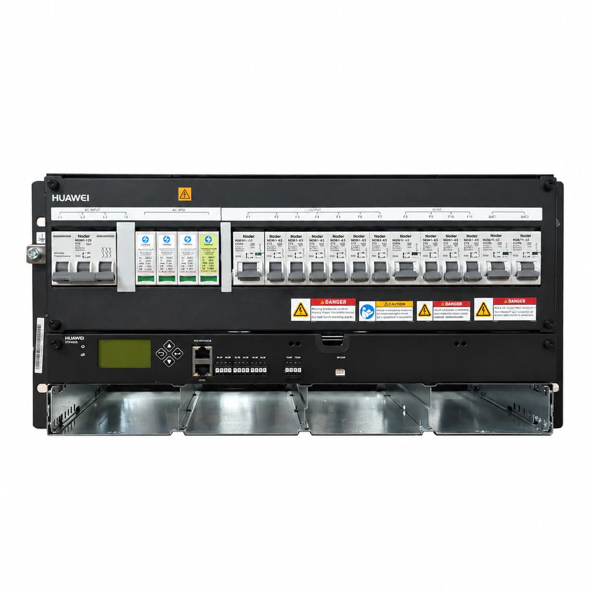
The Huawei ETP48200-C5B6 is a modular 19-inch DC power plant combining AC input surge suppression, high-efficiency conversion, multi-tiered battery Low Voltage Disconnect (LVD), and remote SNMP telemetry.
Information below comes from the current product catalogue. Confirm the controller, software version and configuration of the installed equipment separately.
Nominal DC Output Voltage
-48 V DC
Physical Dimensions Spec
222 (5U) × 442 × 360 mm
Operating Temperature
-40 ~ +65 °C
Rectifier Module Slots
4 × 50A Slots
AC Input Mode
Compatible with 220V single-phase / 380V three-phase
SMU06C/SMU11C Controller ALM LED (Red) steady ON; Rectifier (R4850G2) Power LED OFF, Protection LED steady ON or all LEDs OFF.
Upstream commercial grid blackout, main AC distribution unit (ACDU) circuit breaker manual opening, branch breaker tripping from downstream short-circuit/overload, or auxiliary dry contact triggered on the AC detection board.
1. Check the active alarm log on the SMU display, noting whether it reports 'AC Mains Fail' or 'AC Breaker Trip';
2. Use a multimeter to test voltage across ACDU input terminals to distinguish external utility failure from internal tripping;
3. If utility power is healthy, locate tripped MCB toggle switch; verify downstream circuit has no short-circuit and reclose the breaker;
4. Inspect the MCB auxiliary alarm switch and its wiring to the SMU signal port for open circuits;
5. Confirm automatic transfer switch (ATS) startup if running on a diesel generator; ensure system auto-clears alarm upon utility recovery.
DC_UNDERV / LLVD_BLVD_ACT (DC Bus Undervoltage & LLVD/BLVD Disconnect)
SMU06C/SMU11C Controller ALM LED (Red) flashing or steady ON; Audible buzzer sounds; Contactor disengaged.
Extended AC outage leading to battery depletion. When DC bus falls to the LLVD disconnect threshold (default 45.0 VDC), non-critical loads are shed; at the BLVD threshold (default 43.2 VDC), batteries are disconnected to prevent cell reversal and damage.
1. Deploy an emergency mobile diesel generator immediately to restore AC mains power to the subrack;
2. Access the SMU menu 'Parameters -> Battery Settings' to verify that LLVD and BLVD voltage trip levels align with battery manufacturer specs;
3. Once AC is restored, verify that rectifiers start automatically and initiate boost charging under current limit (typically 0.10C to 0.15C10);
4. Verify that LLVD and BLVD contactors mechanically close as DC voltage rises above their respective reconnection thresholds (>48V/51V);
5. If contactors fail to reclose, perform a manual contactor pull-in test via the SMU diagnostics menu to test driver relays.
REC_COMM_FAIL / SMU_OFFLINE (Rectifier to SMU Controller Communication Failure)
SMU06C/11C controller ALM LED (Red) steady ON; Affected R4850G2 rectifier Protection LED (Yellow) flashing (0.5 Hz), Power LED steady ON.
CAN/RS485 communication pins in the backplane slot bent or oxidized, transceiver fault on SMU mainboard, rectifier slot ID conflict, or ribbon signal bus cable loose between subrack backplane and SMU.
1. Check SMU display to determine whether the issue is isolated to a single slot ('Rectifier N Comm Fail') or affects all modules simultaneously;
2. If isolated to one module, unlock and draw out the unit; inspect the rear connector and backplane pins for bent or recessed pins;
3. Firmly reseat and latch the module; navigate to SMU menu and run 'Rectifier Auto Search / Refresh';
4. If all modules are disconnected, reseat the SMU controller and inspect the internal ribbon cable connecting SMU to backplane;
5. Swap module to an empty working slot; if fault follows the module, replace the rectifier; if slot fails with known-good unit, replace SMU.
BATT_TEMP_HIGH / RUNAWAY_PROT (Battery High Temperature Alarm & Thermal Runaway Protection)
SMU06C/SMU11C Controller ALM LED (Red) steady ON; Rectifier system automatically steps down float voltage or aborts boost charge.
Battery compartment air conditioner failure, severe internal resistance degradation causing battery self-heating, or external battery NTC sensor detached/shorted. Temperature reading exceeds safety threshold (typically >50°C), invoking thermal runaway voltage-drop protection.
1. Scan individual battery jar surfaces with an infrared thermal imaging gun to locate hot spots or mechanical casing bulging;
2. Inspect the NTC sensor connection at the 'TEM_BAT / BATT_T' terminal on the SMU backplane; verify resistance matches standard curve (typically 10 kΩ at 25°C);
3. Verify that temperature compensation slope in the SMU is configured correctly (-3 mV/°C/cell to -5 mV/°C/cell);
4. If thermal runaway is physically detected with swelling or venting, open the corresponding battery string breaker immediately to stop current;
5. If physical battery temperature is normal but SMU reports high temp, replace the damaged NTC probe and attach it to the negative post.
SMU06C/SMU11C Controller ALM LED (Yellow or Red) steady ON; SPD module mechanical status window turns from Green to Red.
Lightning surge or inductive overvoltage on AC/DC distribution causing metal oxide varistors (MOVs) inside the surge protection cartridge to degrade or short-circuit; internal thermal disconnector triggers the remote dry contact to SMU.
1. Inspect the ACDU/DCDU surge suppression panel and check if any SPD cartridge inspection window has turned Red;
2. Verify whether the dedicated SPD backup circuit breaker (MCB) has tripped;
3. Inspect the dry-contact remote signal wiring from the SPD auxiliary switch to the SMU digital input terminal;
4. Open the SPD backup protection breaker, pull out the defective (red window) cartridge, and insert a fresh MOV module of identical rating (e.g., 20 kA / 40 kA 8/20 μs);
5. Reclose the backup breaker; ensure the optical window displays green and verify that the SMU alarm clears automatically.
Access Complete Maintenance & Full Alarm Troubleshooting Manual
This page lists high-frequency critical alarm codes commonly encountered in field maintenance. Comprehensive manufacturer troubleshooting matrices, board-level repair guides, detailed electrical schematics, and firmware commissioning manuals are delivered alongside equipment upon formal project procurement, accompanied by dedicated FAE technical support.
Record the nameplate, system model and controller or module model.
02
Keep the alarm details
Record the full alarm text, indicator colour, timing and whether it persists.
03
Describe recent changes
Note recent replacements, software updates or configuration changes.
Record information visible in the existing interface. Electrical measurements, disassembly and replacement should follow the applicable manufacturer's manual and be performed by qualified personnel.
Related technical articles
Browse the technical guides or send a question about this model.