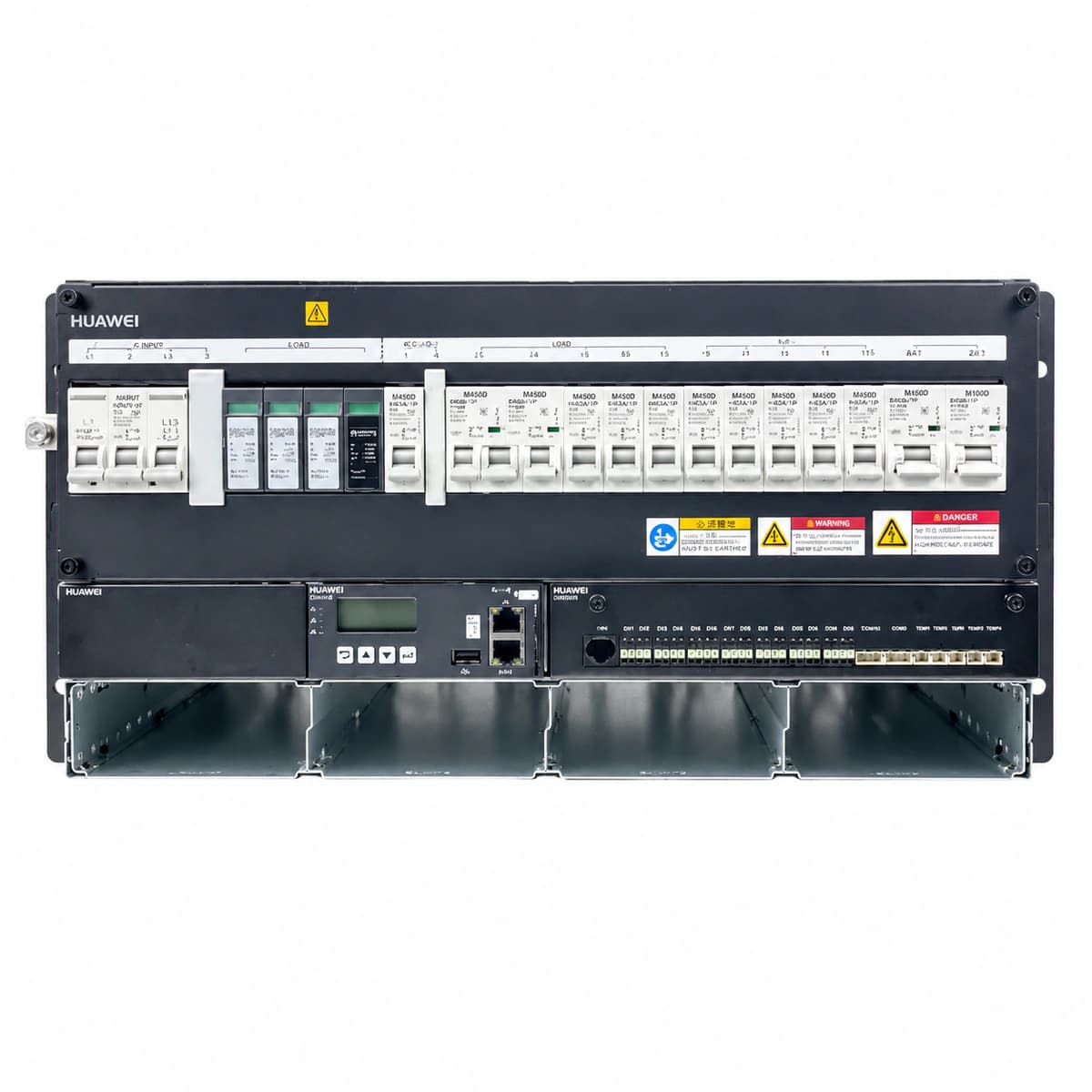
Information below comes from the current product catalogue. Confirm the controller, software version and configuration of the installed equipment separately.
SMU red Fault LED solid ON; Rectifier green Power LED OFF, yellow Protection LED blinking or red Fault LED ON
Mains blackout, AC input circuit breaker tripped, loose AC input terminal screws, phase loss, or AC voltage below operational threshold (<85V AC)
1. Measure line-to-neutral and line-to-line voltages at the AC distribution terminals using a true-RMS multimeter (nominal range: 85V AC-300V AC).
2. Inspect and reset the main AC input breaker and individual rectifier branch breakers if tripped.
3. Verify all AC terminal block wiring screws are tightened to specified torque and inspect for arcing or discoloration.
4. If AC grid is nominal and breakers are closed but the fault persists, reseat the rectifier modules.
OUT_OVER_VOLT (DC Output Overvoltage Lockout)
Faulty rectifier red Fault LED solid ON; SMU red Fault LED solid ON with buzzer sounding
Internal voltage regulation circuit failure inside the rectifier module causing output to exceed hardware safety limit (typically 59.5V DC-60V DC), triggering latching shutdown
1. Identify the slot location of the faulty overvoltage rectifier module via the SMU display or WebUI.
2. Eject the affected rectifier module from the subrack to disconnect it from the DC bus and open its AC input circuit breaker.
3. Wait 3 minutes for internal capacitors to discharge completely, then reinsert; if it latches into red alarm again, replace the module.
4. Verify SMU float and boost voltage parameters to ensure configuration values match battery specifications.
Rectifier yellow Protection LED solid ON; green Power LED blinking or OFF if thermal shutdown tripped; SMU yellow Alarm LED ON
Ambient temperature exceeding operating threshold (>65°C), clogged cabinet air intake/filters restricting airflow, or internal cooling fan jammed/failed
1. Verify site air conditioning operation to bring ambient temperature back to standard specifications (-10°C to +50°C).
2. Inspect the subrack front air intake slots and filters; remove accumulated dust and obstructions.
3. Check if the rectifier fan spins freely; if the fan is seized, noisy, or stationary under load, replace the fan assembly or rectifier module.
4. Allow the unit to cool below restart threshold (typically <55°C) and verify automatic recovery and output power ramping.
SMU red Fault LED solid ON, buzzer sounding, corresponding LLVD/BLVD DC contactors physically tripped open
Prolonged AC power outage leading to complete battery discharge below protection limits (LLVD default ~45.0V DC, BLVD default ~43.2V DC), or battery sampling wire disconnection
1. Deploy an emergency mobile diesel generator to restore AC mains immediately and monitor rectifier startup to restore bus voltage.
2. If essential loads must be urgently restored, manually override and close LLVD/BLVD contactors via SMU control menu.
3. Measure actual battery terminal voltage with a calibrated multimeter to rule out faulty or loose voltage sampling lines.
4. Once power is restored, verify that SMU engages boost charge with battery current limit set correctly (typically 0.1C10 to 0.15C10).
CAN_COMM_FAIL (Rectifier CAN Communication Failure)
Uncommunicative rectifier yellow Protection LED blinking (0.5Hz); SMU yellow Alarm LED solid ON with 'Comm Loss' prompt
Poor contact on backplane CAN-bus gold fingers, bent/damaged communication pins on rectifier connector, faulty SMU CAN transceiver, or ID address conflict
1. Eject the alarming rectifier module and visually inspect the rear gold finger connector pins and backplane socket for bent pins or foreign matter.
2. Reinsert the module firmly and latch the handle securely to ensure positive mating with the subrack backplane.
3. Swap the module into an adjacent vacant slot; if communication recovers, the original slot backplane is defective; if the alarm travels with the module, replace the rectifier.
4. If all rectifiers simultaneously report CAN communication loss, reseat or replace the SMU controller.
Access Complete Maintenance & Full Alarm Troubleshooting Manual
This page lists high-frequency critical alarm codes commonly encountered in field maintenance. Comprehensive manufacturer troubleshooting matrices, board-level repair guides, detailed electrical schematics, and firmware commissioning manuals are delivered alongside equipment upon formal project procurement, accompanied by dedicated FAE technical support.
Record the nameplate, system model and controller or module model.
02
Keep the alarm details
Record the full alarm text, indicator colour, timing and whether it persists.
03
Describe recent changes
Note recent replacements, software updates or configuration changes.
Record information visible in the existing interface. Electrical measurements, disassembly and replacement should follow the applicable manufacturer's manual and be performed by qualified personnel.
Related technical articles
Browse the technical guides or send a question about this model.