Huawei / DC power systems

EPW50-48A Equipment information & support

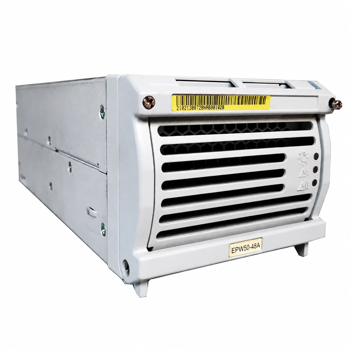
The Huawei EPW50-48A is an industrial-grade switch-mode AC/DC power module utilizing digital DSP control and active PFC to deliver clean regulated -48V DC power with autonomous load balancing.

Equipment information

Brand
Huawei
Equipment model
EPW50-48A
Equipment type
DC power systems
Controller / software version
Confirm against the installed equipment
View full product specifications
EPW50-48A Official Product View 3

Information below comes from the current product catalogue. Confirm the controller, software version and configuration of the installed equipment separately.

Nominal DC Output Voltage
-48 V DC
Rated Output Current
50 A
Power Conversion Efficiency
95.5 %
Physical Dimensions Spec
130 × 85 × 285 mm
AC Input Voltage Range
85 ~ 300 V AC
Operating Temperature
-40 ~ +75 °C

Alarms & troubleshooting

AC_IN_FAIL (AC Input Abnormal/Loss)
Power LED (Green) OFF, Alarm LED (Yellow) steady ON or OFF
AC utility grid outage; input voltage below 85 VAC or above 300 VAC threshold; AC breaker tripped or loose connection.
1. Measure phase-to-neutral voltage at the AC input terminal using a digital multimeter (normal range: 85–300 VAC). 2. Check if the corresponding AC miniature circuit breaker (MCB) in the PDU is tripped and reset if necessary. 3. Verify that the rectifier rear blind-mate connector is seated firmly; reseat the rectifier module.
DC_OVP (DC Output Overvoltage Lockout)
Fault LED (Red) steady ON, Power LED (Green) OFF
Internal PWM loop control failure or shorted output circuit components; incorrect float voltage command issued by controller; bus overvoltage feedback from parallel rectifiers (>59.5 VDC).
1. Remove the module from the subrack, disconnect power, and wait 3 minutes to fully discharge internal capacitors. 2. Reinsert the module; if the red LED turns on immediately, internal hardware is damaged and requires replacement. 3. If it recovers, check the monitoring unit to verify float/boost voltage parameters are set correctly (nominal 53.5 VDC).
OTP (Over-Temperature Protection & Shutdown)
Alarm LED (Yellow) steady ON, Power LED (Green) blinking or OFF
Ambient temperature exceeds operating limits (>+65°C); module air inlet/outlet or dust filters severely clogged; thermal blockage prevents heat dissipation.
1. Inspect the telecom room HVAC system and ensure ambient temperature is maintained near 25°C. 2. Inspect front and rear ventilation grilles; clear accumulated dust using an ESD-safe brush or compressed air. 3. If airflow and ambient conditions are normal, verify fan operation; verify if output automatically recovers once internal temperature drops below 55°C.
FAN_FAIL (Fan Fault / Speed Abnormal)
Fault LED (Red) blinking slowly at 0.5 Hz, Alarm LED (Yellow) OFF
Fan blades mechanically locked by foreign objects; internal tachometer/PWM speed-sensing wire disconnected; worn-out fan bearing causing rotor stall.
1. Visually inspect the front fan grill for debris or foreign objects; gently spin blades manually to check for mechanical resistance. 2. Disconnect the module and check if the internal fan power connector is securely attached to the control board. 3. If there is no physical blockage and wiring is intact but the fan does not spin upon power-up, replace the fan assembly or the entire rectifier module.
COMM_FAIL (CAN-Bus Communication Loss & Current Share Imbalance)
Alarm LED (Yellow) blinking at 0.5 Hz, Power LED (Green) steady ON
CAN-bus communication pin oxidation/poor contact on the backplane; module slot automatic address assignment error; firmware/protocol mismatch with the system monitoring unit (SMU).
1. Inspect backplane gold-finger connectors for oxidation or debris; clean with electronic contact cleaner and reseat firmly. 2. Access the System Monitoring Unit (SMU) interface and verify that the module slot ID is correctly recognized without packet loss. 3. If current sharing imbalance exceeds 5 A across rectifiers, update module firmware via SMU or test the module in an alternate slot.

Access Complete Maintenance & Full Alarm Troubleshooting Manual

This page lists high-frequency critical alarm codes commonly encountered in field maintenance. Comprehensive manufacturer troubleshooting matrices, board-level repair guides, detailed electrical schematics, and firmware commissioning manuals are delivered alongside equipment upon formal project procurement, accompanied by dedicated FAE technical support.

Share on-site information

  1. 01

    Identify the exact model

    Record the nameplate, system model and controller or module model.

  2. 02

    Keep the alarm details

    Record the full alarm text, indicator colour, timing and whether it persists.

  3. 03

    Describe recent changes

    Note recent replacements, software updates or configuration changes.

Record information visible in the existing interface. Electrical measurements, disassembly and replacement should follow the applicable manufacturer's manual and be performed by qualified personnel.

Your model and these details will be added to the enquiry form for you to review before sending.

Related technical articles

Browse the technical guides or send a question about this model.

View all articles

Need a replacement module or supporting equipment?

Confirm the full model, system configuration and compatibility requirements before enquiring about suitable products.

Ask about suitable products

Have a model and an on-site issue?

Share the exact model, alarm text and observed symptoms to help identify relevant information and compatibility requirements.

Request technical support