Huawei / Power management

BBU3910 Baseband Control Unit Equipment information & support

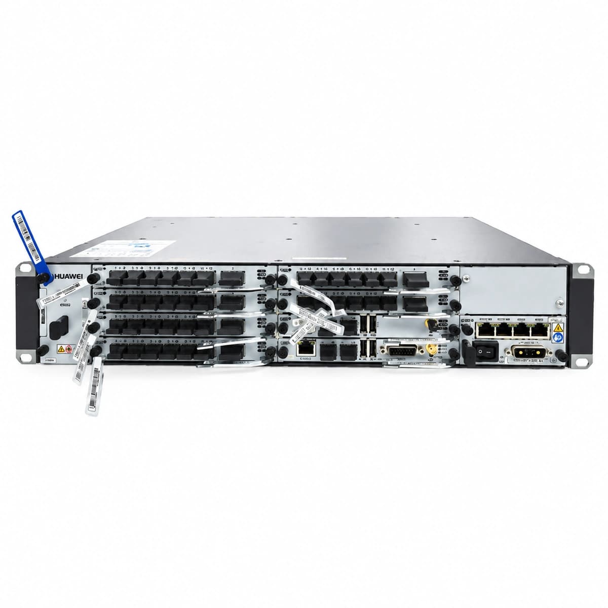
The Huawei BBU3910 is a carrier-grade 2U multi-mode baseband control subrack and power distribution chassis engineered for high-density digital signal processing and centralized power feeding in GSM, UMTS, LTE, and 5G NR distributed base stations.

Equipment information

Brand
Huawei
Equipment model
BBU3910 Baseband Control Unit
Equipment type
Power management
Controller / software version
Confirm against the installed equipment
View full product specifications
Huawei BBU3910 Baseband Control Unit Official Product View 1

Information below comes from the current product catalogue. Confirm the controller, software version and configuration of the installed equipment separately.

Alarms & troubleshooting

ALM-26521 (Input DC Power Out of Specification)
UPEU RUN LED OFF, ALM LED Steady Red
Input DC voltage dropped below -38.4 V DC or exceeded -57 V DC; upstream DCDU/PDU breaker tripped; loose DC terminal screw or reverse polarity.
1. Measure DC voltage at the UPEU input connector using a multimeter to verify nominal -48 V DC (-38.4 V DC to -57 V DC). 2. Inspect the upstream DCDU/PDU circuit breaker feeding the BBU subrack for trip conditions. 3. Tighten power terminal screws and inspect cable crimps for oxidation or excessive voltage drop. 4. If input voltage is verified healthy, reseat or replace the faulty UPEU module.
ALM-26522 (Power Module Hardware Fault)
UPEU ALM LED Steady Red, RUN LED blinking irregularly or OFF
Internal DC-DC power conversion circuit failure; internal protection fuse blown; poor backplane pin contact or overcurrent lockout on UPEU sub-board.
1. Remove the UPEU module and inspect the backplane connector for bent, broken, or burnt pins. 2. Reinsert the UPEU module securely and torque the captive screws to ensure proper backplane seating. 3. Run MML command `DSP BRD: 0;` to inspect UPEU operational state and voltage outputs. 4. If the fault persists, replace the UPEU power module.
ALM-26529 (Fan Module Fault)
FAN STATE LED Steady Red, BBU Main Control ALM LED ON
Fan rotor stalled by foreign debris or heavy dust accumulation; tachometer pulse loss; fan speed control IC failure on the FAN backplane.
1. Pull out the FAN unit and inspect rotors for physical blockage, entangled cables, or severe dust. 2. Clean the air intake mesh and spin blades manually to ensure smooth bearing movement. 3. Execute MML command `DSP FAN: 0;` to identify the failing fan index and query rpm metrics. 4. Reseat the FAN module; if rotation speed remains 0 RPM or unregulated, replace the FAN subassembly.
ALM-26532 (Board Temperature Exceeds Threshold)
Target board ALM LED Steady Red, FAN module running at 100% maximum speed
Ambient temperature in the shelter or outdoor cabinet exceeds 55°C; clogged air intake filter restricting airflow; thermal pad degradation on ASIC chip; partial fan failure.
1. Verify shelter HVAC or outdoor cabinet heat exchanger functionality; lower ambient intake temperature to <45°C. 2. Clean or replace clogged cabinet air filter screens and clear debris around front vents. 3. Execute MML command `DSP BRDTEMP: 0;` to pinpoint the overheating slot and review sensor readings. 4. If environment and filters are normal, reseat the board; replace the board if the thermal sensor or heatsink is damaged.
ALM-26523 (Power Module Communication Failure)
UPEU RUN LED blinking slowly (0.5 Hz), UMPT Main Control ALM LED ON
Backplane I2C/CAN management bus disruption between UMPT and UPEU; loose module seating causing pin disconnect; locked UPEU monitoring microcontroller.
1. Ensure UPEU ejector levers are fully locked and captive screws are torqued down securely. 2. Perform a software reset on the main control board using MML command `RST BRD: 0, 7;` to re-scan the hardware bus. 3. Pull the UPEU module, check the backplane connection interface for dust or bent pins, and reinsert. 4. Replace the UPEU module if communication is not restored; if the issue persists, replace the BBU subrack backplane.

Access Complete Maintenance & Full Alarm Troubleshooting Manual

This page lists high-frequency critical alarm codes commonly encountered in field maintenance. Comprehensive manufacturer troubleshooting matrices, board-level repair guides, detailed electrical schematics, and firmware commissioning manuals are delivered alongside equipment upon formal project procurement, accompanied by dedicated FAE technical support.

Share on-site information

  1. 01

    Identify the exact model

    Record the nameplate, system model and controller or module model.

  2. 02

    Keep the alarm details

    Record the full alarm text, indicator colour, timing and whether it persists.

  3. 03

    Describe recent changes

    Note recent replacements, software updates or configuration changes.

Record information visible in the existing interface. Electrical measurements, disassembly and replacement should follow the applicable manufacturer's manual and be performed by qualified personnel.

Your model and these details will be added to the enquiry form for you to review before sending.

Related technical articles

Browse the technical guides or send a question about this model.

View all articles

Need a replacement module or supporting equipment?

Confirm the full model, system configuration and compatibility requirements before enquiring about suitable products.

Ask about suitable products

Have a model and an on-site issue?

Share the exact model, alarm text and observed symptoms to help identify relevant information and compatibility requirements.

Request technical support