HEFENGQI / UPS power

East EA890 10kVA-120kVA Industrial UPS Equipment information & support

The East EA890 series is a 10kVA to 120kVA 3-phase in/out heavy-duty low-frequency online double-conversion UPS, engineered with a built-in output galvanic isolation transformer and robust IGBT inverter to deliver pure, uninterrupted power under severe industrial electrical environments.

Equipment information

Brand
HEFENGQI
Equipment model
East EA890 10kVA-120kVA Industrial UPS
Equipment type
UPS power
Controller / software version
Confirm against the installed equipment
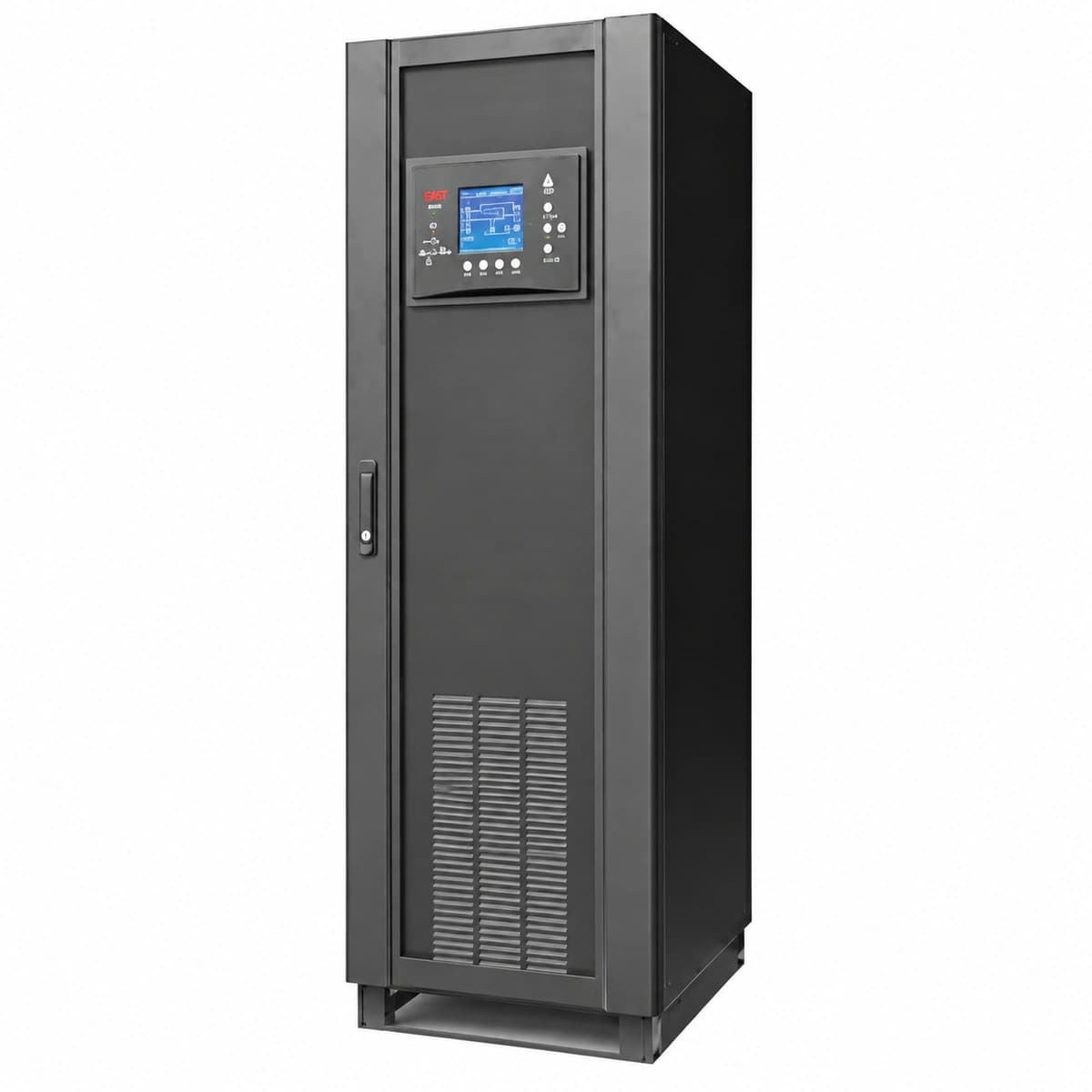
View full product specifications
East EA890 10kVA-120kVA 3-Phase Industrial Low-Frequency Online UPS

Information below comes from the current product catalogue. Confirm the controller, software version and configuration of the installed equipment separately.

Rated System Capacity
10kVA ~ 120kVA 3-Phase In/Out Industrial Frequency Online UPS
Built-in Isolation Transformer
Integrated Industrial Low-Frequency Isolation Transformer (High Surge Withstand)
3-Phase Input Specification
380V / 400V / 415V AC (3-Phase 4-Wire Grid)
Overload Capability
125% for 10 min, 150% for 1 min Overload Capability
Parallel Redundancy
Supports Parallel Redundancy up to 6 Units
Display & Control Panel
Large Touchscreen LCD/LED Graphical User Interface

Alarms & troubleshooting

INV_FAULT (Inverter Hardware Fault / Transfer to Bypass)
FAULT LED solid red, INV LED off, BYPASS LED solid amber, continuous buzzer
Inverter bridge IGBT driver failure, overcurrent puncture, or short-circuit in inverter LC filter capacitors causing hardware latching.
1. Verify critical load has safely switched to static bypass without interruption. 2. Disconnect inverter DC switch and AC output breaker; wait until DC bus capacitors discharge below 36V. 3. Measure IGBT collector-emitter voltage drops and inspect gate drive pulses with an oscilloscope. 4. Replace damaged IGBT module or filter capacitors before cold-start recalibration.
DC_BUS_OV (DC Bus Overvoltage Hardware Lockout)
FAULT LED solid red, REC LED flashing green, rapid intermittent buzzer
Rectifier SCR phase-control loss, severe grid voltage surge, or open-circuit in braking absorption resistor causing DC bus to exceed limit.
1. Disconnect input AC mains immediately; avoid manual reset while live. 2. Measure physical DC bus voltage with a calibrated meter; compare with telemetry to verify voltage sampling resistors. 3. Inspect rectifier SCR gate integrity and snubber RC circuits for breakdown or charring. 4. Clear input voltage anomalies, reset fault via control panel, and restart.
BATT_DISCONN_EOD (Battery Disconnected / End of Discharge)
BATTERY LED flashing amber, ALARM LED solid amber, 2-second beep interval
External battery breaker auxiliary contact open, DC fuse blown, or cells discharged down to End-of-Discharge cutoff threshold.
1. Check external MCCB handle and inline DC fuses; verify contacts are fully seated. 2. Measure open-circuit terminal voltage of the battery bank; confirm if below cutoff (approx. 10.5V/cell for 12V block). 3. Inspect auxiliary status microswitch wiring terminals for loose connections or oxidation. 4. If mains AC is healthy, close the breaker and initiate boost charging to recover cell capacity.
OVER_TEMP (Power Stage & Heatsink Overtemperature Shutdown)
FAULT LED flashing red, TEMP LED solid amber, continuous buzzer
Air intake dust filter blocked, cooling fan jammed/failed, or ambient HVAC failure causing IGBT junction temperature to exceed 90°C.
1. Remove and clean front intake dust filters; ensure roof exhaust louvers are unobstructed. 2. Access LCD diagnostics to inspect temperature telemetry and fan FG/tachometer feedback. 3. Spin fan blades manually to check for bearing seizure; replace defective fan assemblies. 4. Allow heatsink to cool below 65°C before clearing lockout and resuming inverter operation.
OUT_OVERLOAD (Output Overload Bypass Active)
OVERLOAD LED solid amber, BYPASS LED solid amber, INV LED flashing green, pulsing buzzer
Connected load exceeds nominal capacity (e.g. >125% for 10 min or >150% for 1 min), triggering inverter protection transfer to bypass.
1. Review three-phase output load percentages and crest factor on the LCD monitor. 2. Shed non-critical secondary loads immediately; check downstream PDUs for inrush currents or localized ground faults. 3. Once load drops below 90% rated capacity, execute 'Inverter Turn-ON' command via user interface. 4. If load cannot be shed, evaluate parallel N+X capacity expansion.

Access Complete Maintenance & Full Alarm Troubleshooting Manual

This page lists high-frequency critical alarm codes commonly encountered in field maintenance. Comprehensive manufacturer troubleshooting matrices, board-level repair guides, detailed electrical schematics, and firmware commissioning manuals are delivered alongside equipment upon formal project procurement, accompanied by dedicated FAE technical support.

Share on-site information

  1. 01

    Identify the exact model

    Record the nameplate, system model and controller or module model.

  2. 02

    Keep the alarm details

    Record the full alarm text, indicator colour, timing and whether it persists.

  3. 03

    Describe recent changes

    Note recent replacements, software updates or configuration changes.

Record information visible in the existing interface. Electrical measurements, disassembly and replacement should follow the applicable manufacturer's manual and be performed by qualified personnel.

Your model and these details will be added to the enquiry form for you to review before sending.

Related technical articles

Browse the technical guides or send a question about this model.

View all articles

Need a replacement module or supporting equipment?

Confirm the full model, system configuration and compatibility requirements before enquiring about suitable products.

Ask about suitable products

Have a model and an on-site issue?

Share the exact model, alarm text and observed symptoms to help identify relevant information and compatibility requirements.

Request technical support