HEFENGQI / DC power systems

CE+T Inview S Advanced Monitoring Controller Equipment information & support

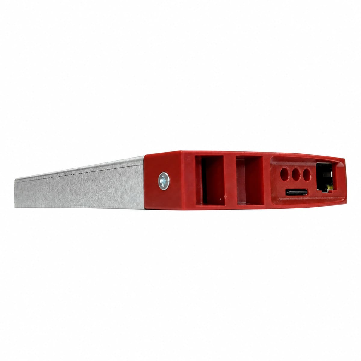
CE+T Inview S is an advanced industrial embedded system monitoring controller engineered for modular DC power and inverter systems, featuring an 18V-60V DC self-powering topology, dual isolated CAN bus links, Fast Ethernet, and configurable relays for unified telemetry and intelligent battery lifecycle management.

Equipment information

Brand
HEFENGQI
Equipment model
CE+T Inview S Advanced Monitoring Controller
Equipment type
DC power systems
Controller / software version
Confirm against the installed equipment
View full product specifications
CE+T Inview S Embedded Power Monitoring Controller 18-60VDC Color Screen

Information below comes from the current product catalogue. Confirm the controller, software version and configuration of the installed equipment separately.

Controller Positioning
Modular Embedded Controller Core for Power & Inverter Systems
Internal Bus Interface
Dual Galvanically Isolated CAN Buses for Millisecond Load Balancing
Network Management Interface
10/100M RJ45 Ethernet Port Supporting Web, SNMP & Modbus
Battery Management Features
Accurate Battery Energy Metering, Thermal Compensation & SOH Testing
Dry Contact Alarm Outputs
Multi-Channel Digital Inputs & Relay Dry Contacts for Emergency Shutdown
Display & Control Interface
High-Resolution Color Multi-Parameter Graphical Display

Alarms & troubleshooting

CAN_COMM_FAIL (CAN Bus Communication Failure)
Controller Alarm LED Red solid, module Comm LED blinking red or off
Loose or damaged RJ45 CAN cable, missing 120-ohm bus termination resistor, duplicate module node address, or damaged CAN transceiver
1. Inspect RJ45 patch cables and daisy-chain connections between the Inview S controller and power modules. 2. Verify that 120-ohm bus termination resistors are correctly placed at both physical ends of the CAN bus. 3. Log in to the Inview S web/LCD interface to review module scan status, identify unresponsive modules, and reseat or replace them.
DC_VOLT_LOW (DC Bus Undervoltage / LVD Alarm)
Controller Alarm LED Red solid, Major alarm relay energized
Prolonged AC utility outage exceeding battery backup, rectifier capacity overload, severely depleted battery string, or incorrect LVD disconnect threshold configuration
1. Check AC input power source; start standby generator or investigate rectifier operational status. 2. Measure DC bus voltage using a calibrated multimeter to verify accuracy against Inview S telemetry. 3. Shed non-critical DC loads to prevent total low-voltage disconnect (LLVD/BLVD), and verify float/boost charge limit settings upon mains restoration.
MOD_FAULT (Power Module Internal Hardware Fault)
Controller Alarm LED Amber solid, faulty module Fault LED Red solid
Internal semiconductor breakdown, output overvoltage shutdown (HVSD) latch, internal cooling fan stall, or auxiliary power board failure inside the module
1. Access the Inview S event log to identify the specific module slot, serial number, and diagnostic code. 2. Disengage and withdraw the faulty module; inspect the rear connector and blind-mate backplane for arcing or pin damage. 3. Insert a spare module of identical rating and firmware; verify automatic recognition and load sharing on the controller UI.
BATT_TEMP_HIGH (Battery High Temperature Alarm)
Controller Alarm LED Amber solid, temperature-compensated float derating active
Battery room HVAC cooling failure, thermal runaway developing during float/boost charge, or shorted/drifted NTC temperature sensor
1. Measure individual battery cell casing temperatures with an infrared thermometer to detect thermal runaway or swelling. 2. Inspect the NTC sensor probe wiring at the Inview S analog input terminals; disconnect and measure resistance to verify sensor integrity. 3. Verify battery compartment HVAC operation; if batteries are hot, force float charge voltage down or disable boost charge in the controller menu.
SPD_TRIP (Surge Protective Device Failure)
Controller Alarm LED Amber solid, SPD module mechanical flag displays red
High-energy lightning surge or utility transient causing MOV degradation, triggering the auxiliary microswitch dry contact to the controller
1. Inspect the SPD cartridges on the AC/DC distribution panel to identify the failed module with the red visual indicator. 2. Verify the continuity and tight seating of the dry contact signal wiring connected to the Inview S digital input (DI) port. 3. Hot-swap the damaged plug-in cartridge with a replacement of identical Uc/Imax ratings and verify alarm clear on Inview S.

Access Complete Maintenance & Full Alarm Troubleshooting Manual

This page lists high-frequency critical alarm codes commonly encountered in field maintenance. Comprehensive manufacturer troubleshooting matrices, board-level repair guides, detailed electrical schematics, and firmware commissioning manuals are delivered alongside equipment upon formal project procurement, accompanied by dedicated FAE technical support.

Share on-site information

  1. 01

    Identify the exact model

    Record the nameplate, system model and controller or module model.

  2. 02

    Keep the alarm details

    Record the full alarm text, indicator colour, timing and whether it persists.

  3. 03

    Describe recent changes

    Note recent replacements, software updates or configuration changes.

Record information visible in the existing interface. Electrical measurements, disassembly and replacement should follow the applicable manufacturer's manual and be performed by qualified personnel.

Your model and these details will be added to the enquiry form for you to review before sending.

Related technical articles

Browse the technical guides or send a question about this model.

View all articles

Need a replacement module or supporting equipment?

Confirm the full model, system configuration and compatibility requirements before enquiring about suitable products.

Ask about suitable products

Have a model and an on-site issue?

Share the exact model, alarm text and observed symptoms to help identify relevant information and compatibility requirements.

Request technical support