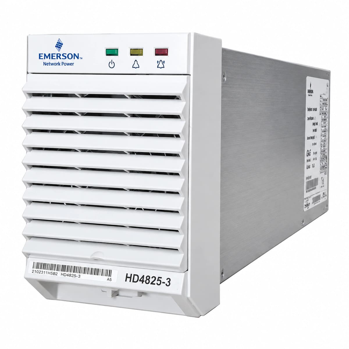
The Emerson HD4825-3 is a high-reliability, hot-swappable switch-mode rectifier module engineered for carrier-grade DC power plants, converting nominal single-phase AC utility into regulated -48V DC power.
Information below comes from the current product catalogue. Confirm the controller, software version and configuration of the installed equipment separately.
Internal secondary feedback loop failure, PWM regulation failure, or external DC bus voltage transient causing hardware latching shutdown.
1. Withdraw the faulted rectifier module from the subrack slot to disconnect it from the backplane.\n2. Measure the common DC bus voltage with a DMM to verify it is within normal limits (-42V DC to -58V DC).\n3. Wait 3 minutes for internal high-voltage capacitors to fully discharge, then reseat the module firmly.\n4. If the red Fault LED immediately illuminates again upon power-up, internal power semiconductors or sensing circuitry are defective; replace the module.
AC_FAIL (AC Mains Input Failure)
Yellow Protection LED solid ON, Green Run LED OFF
Mains blackout, input circuit breaker tripped, or AC input voltage out of operational tolerance (<80V AC undervoltage or >300V AC overvoltage).
1. Check the AC distribution breaker dedicated to the module in the power cabinet to see if it has tripped.\n2. Measure true RMS AC voltage across L and N pins at the module backplane receptacle (nominal: 85V~290V AC).\n3. Inspect the upstream Surge Protective Device (SPD) for degradation or short circuits causing the breaker to open.\n4. Verify upstream ATS (Automatic Transfer Switch) and phase selector switches are supplying stable power.
MOD_OTP (Module Over-Temperature Protection)
Yellow Protection LED solid ON, DC output shut down or linearly derated
Ambient temperature exceeding operational ceiling (>+65°C), clogged cabinet dust filters obstructing intake air, or severe dust accumulation on internal power heatsinks.
1. Inspect the site HVAC equipment and bring ambient room temperature within the rated window (-10°C to +45°C).\n2. Remove and clean or replace cabinet air intake dust filters to restore unrestricted airflow.\n3. Extract the module and blow out accumulated dust from internal heat sinks using dry, low-pressure compressed air.\n4. Once cooled below threshold, the unit resets automatically; if OTP persists at room temperature, replace the module due to a faulty NTC sensor.
FAN_FAIL (Cooling Fan Stall/Failure)
Red Fault LED blinking, Yellow Protection LED solid ON
Foreign object physically blocking fan blades, seized mechanical bearing due to lubricant loss, defective tachometer Hall sensor, or PWM driver circuit fault.
1. Visually inspect the front fan grill for ingested cables, fiber strands, or foreign debris impeding blade movement.\n2. Power off the module and gently spin the fan hub manually to verify smooth rotation without mechanical binding.\n3. Power up the module and observe if the fan spins at high speed during startup self-test; check for nominal 12V DC fan supply.\n4. If 12V DC is present but the fan does not spin or tach feedback is missing, replace the cooling fan assembly or the entire module.
COMM_FAIL (CAN Bus Communication Loss)
Yellow Protection LED blinking, Green Run LED solid ON
Bent or oxidized backplane connector pins, broken CAN_H/CAN_L differential line, missing 120-ohm bus termination resistor, or failed transceiver IC inside the rectifier.
1. Unseat the module and inspect the rear blind-mate connector for bent, pushed-back, or oxidized CAN signal pins.\n2. Check the system controller (e.g., Emerson M221S / M522B) display to verify if all modules or only this specific unit lost polling.\n3. Measure resistance across CAN_H and CAN_L pins on the unpowered backplane bus (nominal is ~60 ohms with dual 120-ohm terminations).\n4. Clean contacts with electronic contact cleaner and reseat firmly; if communications fail to restore in a known good slot, replace the module.
Access Complete Maintenance & Full Alarm Troubleshooting Manual
This page lists high-frequency critical alarm codes commonly encountered in field maintenance. Comprehensive manufacturer troubleshooting matrices, board-level repair guides, detailed electrical schematics, and firmware commissioning manuals are delivered alongside equipment upon formal project procurement, accompanied by dedicated FAE technical support.
Record the nameplate, system model and controller or module model.
02
Keep the alarm details
Record the full alarm text, indicator colour, timing and whether it persists.
03
Describe recent changes
Note recent replacements, software updates or configuration changes.
Record information visible in the existing interface. Electrical measurements, disassembly and replacement should follow the applicable manufacturer's manual and be performed by qualified personnel.
Related technical articles
Browse the technical guides or send a question about this model.