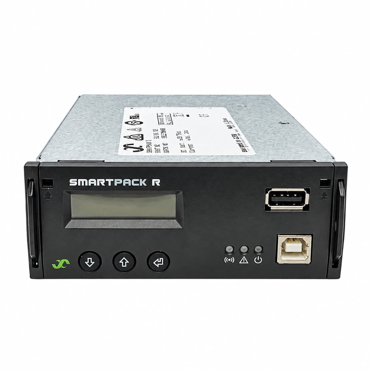
I/O CAN Node Controller (242100.120) Equipment information & support
The Eltek 242100.120 is an industrial-grade CAN bus expansion module engineered to extend analog monitoring, digital sensing, and relay control for Smartpack supervisory systems.
Information below comes from the current product catalogue. Confirm the controller, software version and configuration of the installed equipment separately.
Loose RJ45 patch cable, missing or disabled 120-ohm CAN bus end-terminator, CAN ID address conflict, or open circuit in CAN-H/CAN-L lines.
1. Inspect RJ45 cable connections on both ports of the I/O node; reseat cables until locked.
2. Measure passive resistance between CAN_H and CAN_L with power off (nominal is approx. 60 ohms with both end terminators).
3. Verify the end-of-line 120-ohm termination resistor jumper or switch is correctly enabled.
4. Access the Smartpack controller interface, initiate a CAN node scan, or reassign node address.
PWR_SUPPLY_FAIL (Node Power Supply Failure)
Power/Run LED completely Off or flashing Red
Internal/Auxiliary DC supply input below lower operational threshold (<18VDC), loose supply terminal block, or blown branch protection fuse.
1. Measure DC voltage at the I/O node power terminals using a DMM (verify 18 to 60 VDC operational window).
2. Inspect and tighten terminal block screw clamps; verify no cold or oxidized crimps.
3. Check the branch circuit breaker or inline fuse supplying auxiliary power to the node; replace if blown.
4. If input voltage is verified but unit remains unpowered, power-cycle the module; replace hardware if dead.
TEMP_SENS_FAULT (Battery/Ambient Temperature Sensor Fault)
Status LED solid Yellow or slow blinking Amber (0.5Hz)
NTC temperature probe lead pinched, open-circuit, disconnected from analog terminal block, or sensor element short-circuited outside operational limits (-50°C to +125°C).
1. Check the wiring at the I/O node analog input terminals (Temp/Aux); ensure wires are properly stripped and secured.
2. Disconnect the probe wires and measure resistance across leads (Eltek standard NTC should read approx. 10 kΩ at 25°C); if 0 Ω or infinite, replace probe.
3. Inspect the probe cable along its route for pinching against cabinet doors, sharp edges, or physical damage.
4. If resistance is within spec, recalibrate or reassign the temperature sensor input channel via Smartpack software.
DIG_IN_ALARM (Digital Input Active/Loop Fault)
Status LED fast flashing Red (2Hz) or controller Minor/Major Alarm LED On
Monitored dry-contact peripheral triggered (e.g., SPD surge protector failure contact tripped, MCB breaker open, door switch open, or fuse blown), or monitoring loop disconnected.
1. Identify the triggered DI channel on the Smartpack screen (e.g., DI1: SPD Alarm, DI2: Fuse Alarm).
2. Inspect the associated field equipment: verify if the SPD indicator flag is red, or if an MCB/fuse has physically tripped.
3. Use a DMM to test contact status and voltage level across the DI terminal block to verify open/closed circuit integrity.
4. If peripheral is healthy, verify whether the logic polarity (NO vs. NC) assigned in Smartpack configuration matches the external sensor.
Status LED alternating Red and Yellow, output relay contacts fail to toggle
Excessive inductive load current causing welded relay contacts, blown onboard relay driver IC, or inductive back-EMF surge damaging the output stage.
1. Disconnect external load wiring from the relay terminals; ensure external circuit load does not exceed contact ratings (typically ≤60VDC/0.5A).
2. Perform a Manual Relay Test via the Smartpack controller interface; listen for mechanical clicking and verify continuity with a DMM across NO/NC contacts.
3. If contacts remain permanently open or closed regardless of command, the relay is welded or the driver is damaged.
4. Fit freewheeling/flyback diodes or external interposing relays on inductive loads, and replace the faulty I/O CAN Node controller.
Access Complete Maintenance & Full Alarm Troubleshooting Manual
This page lists high-frequency critical alarm codes commonly encountered in field maintenance. Comprehensive manufacturer troubleshooting matrices, board-level repair guides, detailed electrical schematics, and firmware commissioning manuals are delivered alongside equipment upon formal project procurement, accompanied by dedicated FAE technical support.
Record the nameplate, system model and controller or module model.
02
Keep the alarm details
Record the full alarm text, indicator colour, timing and whether it persists.
03
Describe recent changes
Note recent replacements, software updates or configuration changes.
Record information visible in the existing interface. Electrical measurements, disassembly and replacement should follow the applicable manufacturer's manual and be performed by qualified personnel.
Related technical articles
Browse the technical guides or send a question about this model.