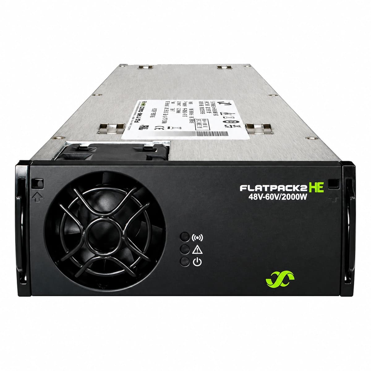
Flatpack2 48/3000 WOR HE (241115.705) Equipment information & support
The Flatpack2 48/3000 WOR HE (241115.705) is a carrier-grade, switch-mode AC/DC power rectifier offering Wide Output Range (WOR) and High Efficiency (HE) performance.
Information below comes from the current product catalogue. Confirm the controller, software version and configuration of the installed equipment separately.
Green Power LED off, Yellow Warning LED solid on (powered via DC bus)
AC mains blackout, AC input voltage dropped below 85 VAC cutoff threshold, individual slot AC breaker tripped, or surge protector failure.
1. Measure AC input terminal voltage at the shelf backplane slot using a DMM to confirm whether phase voltage is within 185-275 VAC (full power) or 85-185 VAC (derated).
2. Inspect the individual branch MCB in the AC distribution unit (ACDU) feeding this rectifier slot and reset if tripped.
3. Reseat the module firmly into the power shelf; if mains voltage is normal but the alarm persists without DC output, replace the rectifier unit.
HVSD_ALARM (Output Overvoltage Shutdown)
Red Alarm LED solid on, Green Power LED off
Rectifier output exceeded selective hardware overvoltage protection threshold (typically 58.5-59.5 VDC), initiating locked shutdown to safeguard DC bus loads.
1. Access the Smartpack controller interface, check alarm logs, and verify actual DC bus voltage against configured high-voltage alarm thresholds.
2. Disengage the rectifier partially from the backplane connectors and leave unpowered for at least 30 seconds to discharge capacitors and clear the HVSD latch.
3. Reseat the module; if it re-latches into red LED shutdown immediately upon restart, the internal feedback loop or power stage has failed and the module must be replaced.
TEMP_SHUTDOWN (Rectifier Thermal Shutdown)
Yellow Warning LED flashing (derating) or Red Alarm LED solid on (shutdown), Green Power LED off
Internal power heatsink temperature exceeded safe operating limit (>85°C) due to ambient room HVAC failure, blocked front fascia air inlets, or airflow restriction.
1. Verify telecom shelter HVAC cooling systems and ensure ambient temperature at the cabinet air intake is below 45°C.
2. Inspect the front fascia grille and rear exhaust ports, cleaning accumulated dust and debris using an ESD-safe brush or dry compressed air.
3. Check system load distribution across all rectifiers via the Smartpack controller; the module will automatically resume normal operation once the internal temperature normalizes.
FAN_FAIL (Rectifier Fan Failure)
Red Alarm LED solid on, or Yellow Warning LED flashing accompanied by 50% power derating
Mechanical rotor lockup on the internal brushless DC fan, lost tachometer speed feedback signal, loose fan connector, or defective fan drive circuitry.
1. Extract the rectifier module and spin the fan impeller manually to verify whether bearings rotate freely without mechanical binding or obstructions.
2. Clear accumulated dust inside the fan chamber with dry compressed air, inspecting the 4-pin fan harness connection for loose seating.
3. Reseat the module and observe if the fan executes its spin-up routine during self-test; replace the fan assembly or entire rectifier if speed feedback remains missing.
CAN_COMM_FAIL (CAN Bus Communication Failure)
Yellow Warning LED flashing at 0.5 Hz, Green Power LED remains solid on
CAN-bus communication lost between rectifier and Smartpack controller, oxidized backplane connector pins, loose shelf interconnect cabling, or missing 120-ohm bus termination resistor.
1. Verify that the rectifier has safely switched to autonomous failsafe mode (typically producing standard float output of 53.5 VDC without active current sharing).
2. Unseat the module, inspect the rear blind-mate interface pins for bending or oxidation, clean with isopropyl alcohol, and reseat firmly.
3. Check inter-shelf RJ45 CAN patch cords and verify that the 120-ohm bus terminators are installed; if all modules drop communication simultaneously, replace the interconnect cable or the Smartpack controller.
Access Complete Maintenance & Full Alarm Troubleshooting Manual
This page lists high-frequency critical alarm codes commonly encountered in field maintenance. Comprehensive manufacturer troubleshooting matrices, board-level repair guides, detailed electrical schematics, and firmware commissioning manuals are delivered alongside equipment upon formal project procurement, accompanied by dedicated FAE technical support.
Record the nameplate, system model and controller or module model.
02
Keep the alarm details
Record the full alarm text, indicator colour, timing and whether it persists.
03
Describe recent changes
Note recent replacements, software updates or configuration changes.
Record information visible in the existing interface. Electrical measurements, disassembly and replacement should follow the applicable manufacturer's manual and be performed by qualified personnel.
Related technical articles
Browse the technical guides or send a question about this model.