Eltek / DC power systems

Flatpack2 48/2000 HE Equipment information & support

Eltek Flatpack2 48/2000 HE delivers benchmark 96.5% high-efficiency conversion in a 1U slim form factor (-48V/40A), significantly cutting OPEX for operators.

Equipment information

Brand
Eltek
Equipment model
Flatpack2 48/2000 HE
Equipment type
DC power systems
Controller / software version
Confirm against the installed equipment
View full product specifications
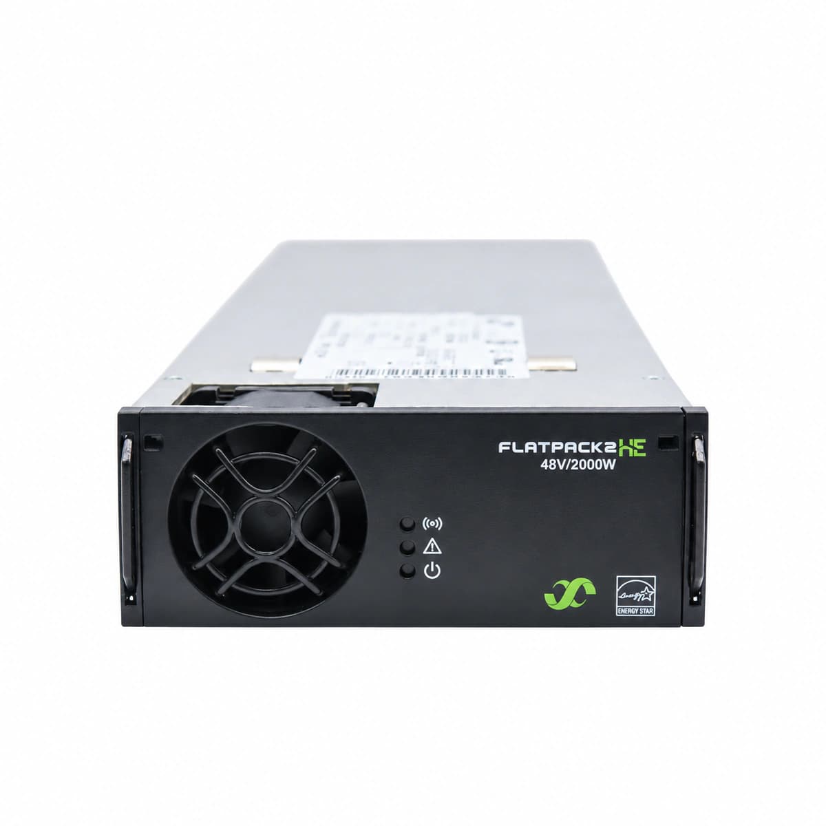
Flatpack2 48/2000 HE Official Product View 1

Information below comes from the current product catalogue. Confirm the controller, software version and configuration of the installed equipment separately.

AC Input Voltage Range
85VAC ~ 300VAC (Nominal 185~275VAC) VAC
Nominal DC Output Voltage
-48 V DC
Cooling Method
Front-to-rear airflow cooling with a stepless variable-speed DC fan
Physical Dimensions Spec
41.5 (1U) × 109 × 327 mm

Alarms & troubleshooting

AC_MAINS_FAIL (AC Mains Failure / Out of Range)
Green LED OFF, Red LED solid ON (powered via system DC bus)
AC grid blackout, branch breaker tripped, or AC input voltage outside 85VAC–300VAC operating range.
1. Measure True-RMS AC voltage at rectifier rear connector pins (L-N); 2. Inspect upstream input circuit breaker (MCB) for tripping or loose terminations; 3. Verify grid frequency is within 45–66 Hz; 4. Reseat rectifier module; if fault persists despite valid AC input, replace unit.
OUTPUT_OVP_LOCKOUT (DC Overvoltage Shutdown / HVSD)
Red LED solid ON, Green LED OFF, output disabled and locked
Internal DC-DC feedback loop failure, external battery/generator surge backfeed, or output voltage exceeded selective HVSD limit (typically 59.5VDC).
1. Unseat the module and verify actual DC bus voltage is normal (53.5–54.5V); 2. Check Smartpack controller OVP threshold configuration; 3. Disconnect AC power for at least 30 seconds to discharge internal DC rail and clear latch; 4. Reinsert module; if HVSD triggers immediately, internal switching component is damaged, replace module.
OVER_TEMP_ALARM (Thermal Derating / High Temp Shutdown)
Yellow LED ON during derating; Red LED ON, Green LED OFF on thermal shutdown
Cabinet air intake filter clogged, ambient air temperature exceeds 55°C, front-to-back ventilation obstructed, or heavy heatsink dust accumulation.
1. Verify unobstructed clearance at front inlet grille and rear exhaust chassis; 2. Clean or replace cabinet air dust filter; 3. Inspect site HVAC cooling operation to bring ambient inlet below 45°C; 4. Allow heatsink to cool; rectifier automatically resumes full power once internal temperature falls below hysteresis point.
FAN_FAIL (Fan Malfunction / Tachometer Fault)
Red LED flashing or solid ON, module derates maximum output current or halts
Fan rotor mechanically seized, physical debris obstruction, broken tachometer feedback wire, or fan drive circuit failure.
1. Hot-swap remove module and visually inspect front fan impeller for physical obstructions; 2. Manually rotate blades using a non-conductive tool to check for mechanical bearing friction; 3. Blow dry compressed air to clear particulate binding; 4. Reinsert module; if the fan fails to spin at self-test or error persists, replace fan assembly or module.
CAN_COMM_FAIL (CAN Bus Communication Loss / Autonomous Mode)
Yellow LED blinking or Green LED blinking (0.5 Hz), unit operates in autonomous mode
Backplane gold-finger CAN pin misalignment/oxidation, Smartpack controller offline, CAN termination resistor mismatch (missing 120Ω), or damaged internal CAN transceiver.
1. Confirm Smartpack controller is powered and operating normally; 2. Withdraw module and inspect rear edge pins for corrosion, bent contacts, or contamination; 3. Measure bus resistance across CAN_H and CAN_L with system powered down (should measure ~60Ω with two 120Ω terminators); 4. Reseat module; if adjacent rectifiers communicate fine, replace the faulty rectifier.

Access Complete Maintenance & Full Alarm Troubleshooting Manual

This page lists high-frequency critical alarm codes commonly encountered in field maintenance. Comprehensive manufacturer troubleshooting matrices, board-level repair guides, detailed electrical schematics, and firmware commissioning manuals are delivered alongside equipment upon formal project procurement, accompanied by dedicated FAE technical support.

Share on-site information

  1. 01

    Identify the exact model

    Record the nameplate, system model and controller or module model.

  2. 02

    Keep the alarm details

    Record the full alarm text, indicator colour, timing and whether it persists.

  3. 03

    Describe recent changes

    Note recent replacements, software updates or configuration changes.

Record information visible in the existing interface. Electrical measurements, disassembly and replacement should follow the applicable manufacturer's manual and be performed by qualified personnel.

Your model and these details will be added to the enquiry form for you to review before sending.

Related technical articles

Browse the technical guides or send a question about this model.

View all articles

Need a replacement module or supporting equipment?

Confirm the full model, system configuration and compatibility requirements before enquiring about suitable products.

Ask about suitable products

Have a model and an on-site issue?

Share the exact model, alarm text and observed symptoms to help identify relevant information and compatibility requirements.

Request technical support