Eltek / DC power systems

Flatpack2 48/1500 HE Solar Equipment information & support

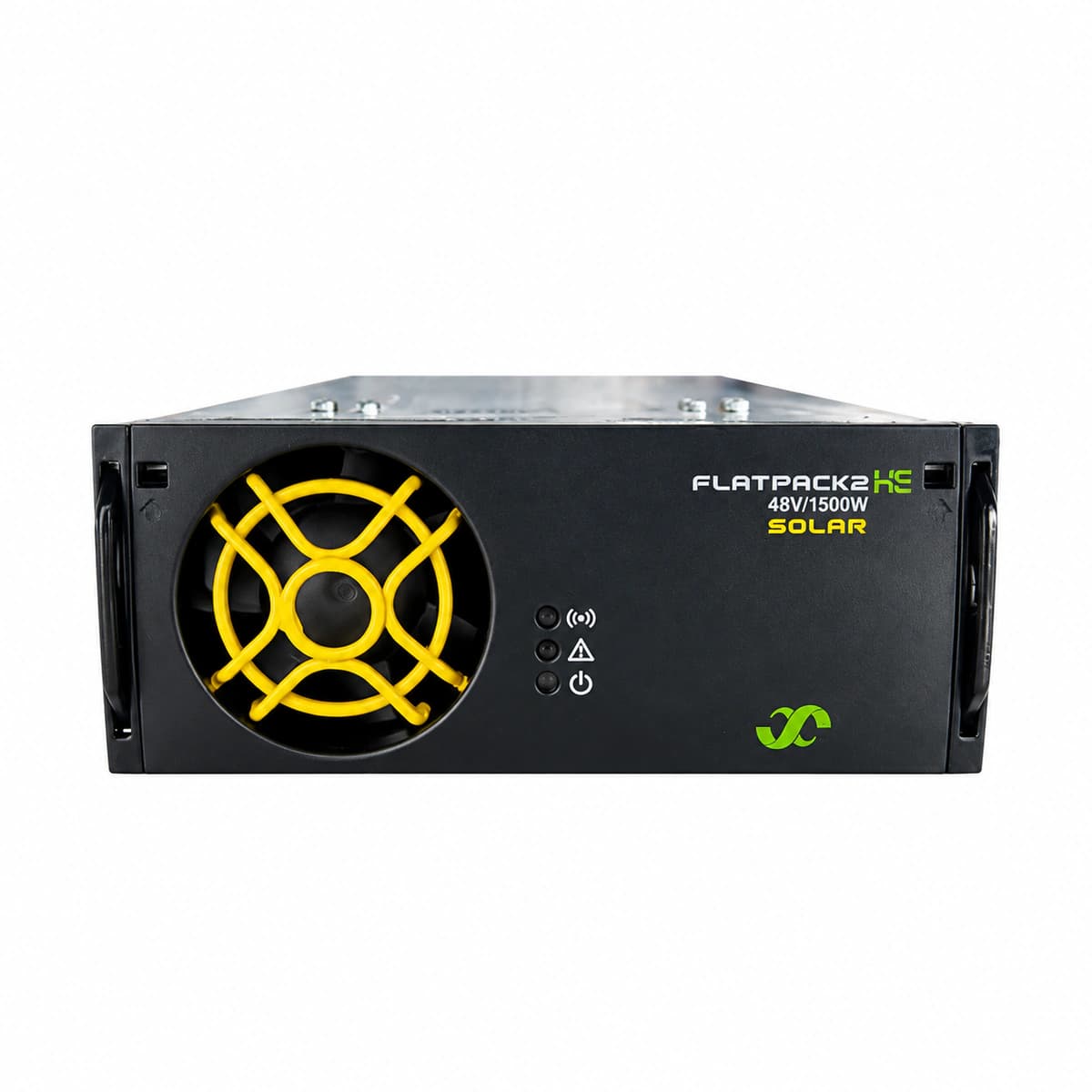
The Eltek Flatpack2 48/1500 HE Solar (Part No. 241115.650) is a high-efficiency solar MPPT DC/DC converter module delivering 1500W at -48V DC, engineered for hybrid telecom power applications with hot-swap flexibility.

Equipment information

Brand
Eltek
Equipment model
Flatpack2 48/1500 HE Solar
Equipment type
DC power systems
Controller / software version
Confirm against the installed equipment
View full product specifications
Flatpack2 48/1500 HE Solar Official Product View 3

Information below comes from the current product catalogue. Confirm the controller, software version and configuration of the installed equipment separately.

Rated Output Power
1500 W
Nominal Output Voltage
-48 VDC
Rated Output Current
31.2 A
Output Voltage Range
-43.5 ~ -57.6 VDC
AC Input Voltage Range
DC 80 ~ 400 V (PV string MPPT input range)
Power Conversion Efficiency
96.5%; MPPT tracking efficiency > 99%

Alarms & troubleshooting

PV_IN_FAIL (PV Input Abnormal)
Yellow LED solid, Green LED off
PV string input voltage below MPPT start threshold (<90VDC), exceeding maximum Voc limit (>400VDC), reversed PV polarity, or string MCB/fuse tripped
1. Measure the PV array open-circuit DC voltage across input pins with a multimeter to verify it is within the 100V-350V operational MPPT window. 2. Verify string polarity with a voltmeter to eliminate reversed wiring and check PV array insulation resistance to ground. 3. Inspect solar combiner box DC fuses and circuit breakers; reset tripped switches and re-seat the module into the subrack to confirm power-up.
OUT_OVP (DC Output Overvoltage Lockout)
Red LED solid, Green LED off
Internal DC-DC feedback loop failure, shorted secondary power MOSFETs, or bus voltage exceeding hardware trip threshold (>59.5VDC) causing latching shutdown
1. Eject the module from the shelf handle latch to disconnect DC power, wait 30 seconds for internal capacitors to discharge, then reinsert to reset the latch. 2. Query the Smartpack controller to verify system float/boost voltage setpoints and measure common DC bus voltage to rule out external charging interference. 3. If the red LED turns solid immediately upon reinsertion, internal power components are damaged; replace the module with an identical spare.
OVER_TEMP (Over-Temperature Derating / Shutdown)
Yellow LED flashing during derating; Yellow LED solid and Green LED off during thermal shutdown
Cabinet cooling ventilation restricted, dust filter clogged, ambient operating temperature exceeding +55°C, or module heatsink thermistor exceeding trip limit
1. Inspect front intake and rear exhaust grilles; clean clogged air filters and remove obstructions around the subrack. 2. Measure the cabinet internal air temperature and verify that outdoor cabinet air conditioner or extractor fans are operating. 3. Allow the module heatsink to cool down; operation will auto-recover. If the alarm persists at normal room temperature, replace the module due to a faulty internal NTC thermistor.
FAN_FAIL (Cooling Fan Locked / Failure)
Red LED solid, Yellow LED off
Brushless DC fan bearing seized, foreign debris blocking fan blades, tachometer feedback wire open, or internal fan driver circuitry failure
1. Remove the module and visually inspect the front fan blades for foreign objects or physical obstruction; spin gently to verify smooth rotation. 2. Clean dust and debris from the fan impeller and housing using dry compressed air. 3. Reinsert the module to trigger the power-on fan self-test; if the fan does not spin or tachometer fault persists, replace the fan assembly or swap the module.
CAN_FAIL (CAN Bus Communication Failure)
Yellow LED flashing slowly (0.5Hz), Green LED solid
Poor contact on module rear connector CAN pins, missing or damaged 120-ohm bus termination resistor, short-circuited CAN wiring, or Smartpack controller freeze
1. Verify that the module is operating in autonomous failsafe mode (maintaining standard 48V float output without MPPT regulation). 2. Unseat the module, inspect and clean the rear gold-plated CAN connectors with electrical contact cleaner, and firmly re-dock into the shelf. 3. Check that the 120-ohm CAN bus terminators are installed at both ends of the subrack chain; reboot the Smartpack controller if all modules report comms loss.

Access Complete Maintenance & Full Alarm Troubleshooting Manual

This page lists high-frequency critical alarm codes commonly encountered in field maintenance. Comprehensive manufacturer troubleshooting matrices, board-level repair guides, detailed electrical schematics, and firmware commissioning manuals are delivered alongside equipment upon formal project procurement, accompanied by dedicated FAE technical support.

Share on-site information

  1. 01

    Identify the exact model

    Record the nameplate, system model and controller or module model.

  2. 02

    Keep the alarm details

    Record the full alarm text, indicator colour, timing and whether it persists.

  3. 03

    Describe recent changes

    Note recent replacements, software updates or configuration changes.

Record information visible in the existing interface. Electrical measurements, disassembly and replacement should follow the applicable manufacturer's manual and be performed by qualified personnel.

Your model and these details will be added to the enquiry form for you to review before sending.

Related technical articles

Browse the technical guides or send a question about this model.

View all articles

Need a replacement module or supporting equipment?

Confirm the full model, system configuration and compatibility requirements before enquiring about suitable products.

Ask about suitable products

Have a model and an on-site issue?

Share the exact model, alarm text and observed symptoms to help identify relevant information and compatibility requirements.

Request technical support