Eltek / DC power systems

Eltek Smartpack S Controller Equipment information & support

The Eltek Smartpack S (Part Number: 242100.400) is a high-reliability, plug-in miniature digital control unit engineered for compact telecom DC power systems, operating across a wide 18V to 60V DC supply range, utilizing a high-speed CAN bus topology to synchronize rectifiers and providing comprehensive Ethernet-based SNMPv3/Web remote administration with advanced battery lifecycle management.

Equipment information

Brand
Eltek
Equipment model
Eltek Smartpack S Controller
Equipment type
DC power systems
Controller / software version
Confirm against the installed equipment
View full product specifications
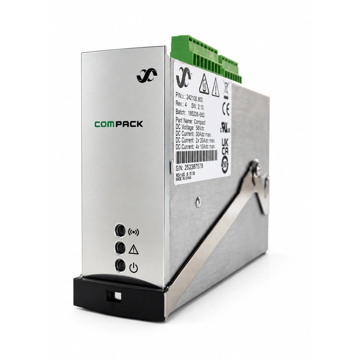
Eltek Smartpack S Controller Compact Power System Monitor (242100.400) Official Studio Photo 4

Information below comes from the current product catalogue. Confirm the controller, software version and configuration of the installed equipment separately.

Display Type
OLED High Definition Digital Display
Internal Bus Interface
CAN Bus High-Speed Digital Interconnection
Remote Network Interface
Ethernet 10/100M RJ45 (Web/SNMPv3 Supported)
Battery Management Features
Advanced Smart Battery Care & Auto Float Algorithm
Dry Contact I/O Channels
6 User-Programmable Dry Contact I/O Ports
Operating Voltage DC
18V DC ~ 60V DC Wide Operating Range

Alarms & troubleshooting

COMM_FAIL_CAN (CAN Bus Communication Failure)
Controller Amber Warning LED solid, affected Rectifier Amber LED flashing
Internal CAN bus communication interrupted between controller and rectifiers/peripherals, incorrect termination resistors, or backplane pin damage
1. Verify Smartpack S controller seating in the backplane; reseat firmly. 2. Verify 120Ω CAN end-of-line termination jumpers on system shelf. 3. Measure resistance between CAN_H and CAN_L with system de-energized (nominal ~60Ω). 4. Reseat or isolate rectifier modules individually to detect the transceiver dragging down the bus.
MAINS_FAIL (AC Mains Input Failure)
Controller Red Alarm LED solid, Green Power LED operating under battery supply
Upstream AC feed outage, tripped AC circuit breaker, low line voltage (<85VAC), or phase loss
1. Measure phase-to-neutral voltage at AC distribution panel. 2. Inspect upstream circuit breakers and AC surge protective device (SPD) status flags. 3. Check detected AC voltages on Smartpack S front screen or web UI under 'System Voltages'. 4. If AC voltage is normal, verify configured high/low mains disconnect alarm thresholds.
LVBD_ACTIVE (Low Voltage Battery Disconnect Active)
Controller Red Alarm LED solid, audible buzzer active, LVBD contactor open
Extended AC outage leading to battery depletion reaching disconnect limit (e.g., 43.2V on 48V float), contactor opened to prevent cell damage
1. Deploy mobile generator immediately to restore AC input power to the plant. 2. Once rectifiers power up, verify whether the controller automatically closes the contactor above reconnect voltage. 3. If AC is restored but contactor fails to pick up, issue a 'Manual LVD Reconnect' command via keypad/web interface. 4. Monitor battery recharge current limit settings to prevent thermal stress during recovery.
BATT_TEMP_HIGH (Battery High Temperature Alarm)
Controller Amber Warning LED flashing, turning Red Alarm solid if critical threshold exceeded
Battery room HVAC failure, early stages of thermal runaway, drifted NTC temperature probe, or shorted sensor cabling
1. Scan individual battery blocks with an infrared thermometer to detect hot spots or swelling. 2. Inspect room HVAC operation and verify controller temp-compensated float voltage is decreasing properly. 3. Disconnect temperature sensor from Smartpack S input and verify resistance (typically 10kΩ at 25°C). 4. If thermal runaway is suspected, immediately trip the corresponding battery string breaker.
RECT_FAIL (Rectifier Module Failure / Major Alarm)
Controller Red Alarm LED solid, faulty Flatpack2 module Red Error LED solid
Internal power stage semiconductor failure, High Voltage Shutdown (HVSD) latch-up, fan lockup, or blown output fuse
1. Access Smartpack S menu/Web UI to check specific rectifier fault register (e.g., HVSD, Fan Fail, Over-Temp). 2. Unlatch and slide out the faulty rectifier; inspect backplane rear connector for burnt pins. 3. Verify fan spins freely and airflow path is unblocked; re-insert after 3 minutes for a power cycle. 4. If red LED persists and module fails to deliver current, replace with a matched Flatpack2 spare.

Access Complete Maintenance & Full Alarm Troubleshooting Manual

This page lists high-frequency critical alarm codes commonly encountered in field maintenance. Comprehensive manufacturer troubleshooting matrices, board-level repair guides, detailed electrical schematics, and firmware commissioning manuals are delivered alongside equipment upon formal project procurement, accompanied by dedicated FAE technical support.

Share on-site information

  1. 01

    Identify the exact model

    Record the nameplate, system model and controller or module model.

  2. 02

    Keep the alarm details

    Record the full alarm text, indicator colour, timing and whether it persists.

  3. 03

    Describe recent changes

    Note recent replacements, software updates or configuration changes.

Record information visible in the existing interface. Electrical measurements, disassembly and replacement should follow the applicable manufacturer's manual and be performed by qualified personnel.

Your model and these details will be added to the enquiry form for you to review before sending.

Related technical articles

Browse the technical guides or send a question about this model.

View all articles

Need a replacement module or supporting equipment?

Confirm the full model, system configuration and compatibility requirements before enquiring about suitable products.

Ask about suitable products

Have a model and an on-site issue?

Share the exact model, alarm text and observed symptoms to help identify relevant information and compatibility requirements.

Request technical support