Eltek / DC power systems

Eltek Smartpack R Controller Equipment information & support

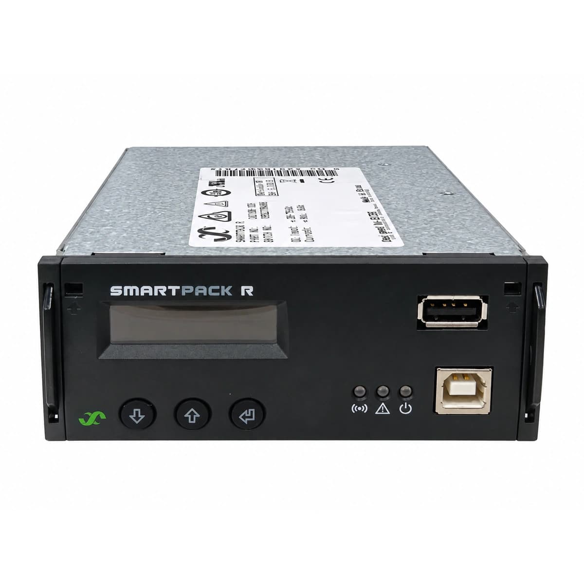
The Eltek Smartpack R (242100.120) is a carrier-grade 1U standalone rack-mounted central supervisory unit engineered for DC telecom power systems, operating across an ultra-wide 18V-60V DC input, utilizing a fully digitized CAN bus to govern rectifiers, batteries, and multi-protocol network communications.

Equipment information

Brand
Eltek
Equipment model
Eltek Smartpack R Controller
Equipment type
DC power systems
Controller / software version
Confirm against the installed equipment
View full product specifications
ELTEK Eltek Smartpack R Controller 1U Rack-Mount Central Monitoring Unit (242100.120) Official Studio Photo 2

Information below comes from the current product catalogue. Confirm the controller, software version and configuration of the installed equipment separately.

Display Type
High-Contrast LCD Display + Navigation Keys
Internal Bus Interface
All-Digital CAN High-Speed Internal System Bus
Remote Network Interface
Ethernet RJ45 (Web/SNMP/Modbus Protocols Supported)
Smart Battery Care Function
Smart Battery Balancing, Temp Compensation & Discharge Test
I/O Interface Channels
Multi-Channel Programmable Dry Contact & Sensor Ports
Operating Voltage DC
18V DC ~ 60V DC Wide Voltage Supply

Alarms & troubleshooting

CAN_COMM_FAIL (CAN Bus Communication Failure)
Yellow Alarm LED steady, comm loss icon flashing on LCD
CAN-bus communication cable disconnected, loose, missing 120-ohm termination resistor, or address conflict between Smartpack R and Flatpack rectifiers/I/O monitors.
1. Check RJ45 CAN bus cabling on the rear panel of the controller for secure seating. 2. Measure total CAN bus loop resistance (nominal 60 ohms with both 120-ohm terminators in place). 3. Reseat rectifiers displaying yellow LEDs to re-initialize nodes. 4. Rescan the CAN bus topology via Smartpack R front menu or WebPower interface.
DC_HIGH_VOLT (DC High Voltage Shutdown)
Red Alarm LED steady, audible buzzer active, rectifier red LEDs illuminated with output shutdown
Busbar DC voltage exceeded the overvoltage trip threshold (e.g., 59.5V), typically triggered by a malfunctioning rectifier runaway, load drop, or faulty voltage sense wire.
1. Measure actual bus voltage with a calibrated digital multimeter to verify the fault. 2. Remove rectifiers sequentially to identify and isolate the runaway unit. 3. Inspect voltage sense cable connections to the Smartpack R. 4. Verify OVP thresholds in the controller configuration and perform a software latch clear/reset.
LVD_DISCONNECT (Low Voltage Disconnect Activated)
Red Alarm LED solid ON, LCD shows LVD open, major alarm relay activated
Extended AC mains outage causing battery discharge below the programmed LVD disconnect threshold (typically 43.2V), or LVD contactor coil drive circuit open/fuse blown.
1. Verify whether AC mains has returned and check direct battery terminal voltage. 2. Inspect the LVD control fuse and wiring from the Smartpack R output terminals to the contactor. 3. If AC is restored but contactor remains open, verify the reconnect voltage setting or execute manual override via the front panel. 4. Measure contactor coil resistance to rule out open circuit.
MAINS_FAIL (AC Mains Failure)
Yellow Alarm LED flashing, rectifier AC input LEDs OFF, system running on battery discharge
Upstream AC distribution breaker tripped, grid voltage below 85VAC undervoltage cutoff, phase loss, or power blackout.
1. Verify the status of the upstream AC distribution breakers and surge protective device (SPD) breakers. 2. Measure phase-to-neutral and phase-to-phase AC voltages at the rack terminals (nominal 85–275VAC). 3. Inspect AC mains monitor sensor connections on the Smartpack R terminal block. 4. Track remaining battery reserve runtime and dispatch mobile generator if necessary.
BATT_TEMP_HIGH (Battery High Temperature)
Yellow Alarm LED steady, battery temperature indicator exceeding threshold on LCD
HVAC system failure causing high ambient temperature, battery cell thermal runaway during float charge, or defective/shorted NTC temperature probe.
1. Inspect battery blocks with an infrared thermometer to detect localized cell swelling or thermal runaway. 2. Verify NTC temperature sensor resistance and wiring to Smartpack R analog input (nominal 10k ohms at 25°C). 3. Check shelter HVAC operational status. 4. If high temperature is genuine, reduce float charge voltage temporarily or ensure temperature-compensated charging is operating correctly.

Access Complete Maintenance & Full Alarm Troubleshooting Manual

This page lists high-frequency critical alarm codes commonly encountered in field maintenance. Comprehensive manufacturer troubleshooting matrices, board-level repair guides, detailed electrical schematics, and firmware commissioning manuals are delivered alongside equipment upon formal project procurement, accompanied by dedicated FAE technical support.

Share on-site information

  1. 01

    Identify the exact model

    Record the nameplate, system model and controller or module model.

  2. 02

    Keep the alarm details

    Record the full alarm text, indicator colour, timing and whether it persists.

  3. 03

    Describe recent changes

    Note recent replacements, software updates or configuration changes.

Record information visible in the existing interface. Electrical measurements, disassembly and replacement should follow the applicable manufacturer's manual and be performed by qualified personnel.

Your model and these details will be added to the enquiry form for you to review before sending.

Related technical articles

Browse the technical guides or send a question about this model.

View all articles

Need a replacement module or supporting equipment?

Confirm the full model, system configuration and compatibility requirements before enquiring about suitable products.

Ask about suitable products

Have a model and an on-site issue?

Share the exact model, alarm text and observed symptoms to help identify relevant information and compatibility requirements.

Request technical support