Eltek / DC power systems

Eltek CT0S0201 Subrack System Equipment information & support

The ELTEK CT0S0201 is a carrier-grade, standard 19-inch embedded -48V DC power subrack integrating rectifier module slots, a dedicated Smartpack controller bay, and combined AC/DC distribution, engineered to deliver up to 150A-300A system capacity with integrated Low Voltage Disconnect (LVDS) battery protection.

Equipment information

Brand
Eltek
Equipment model
Eltek CT0S0201 Subrack System
Equipment type
DC power systems
Controller / software version
Confirm against the installed equipment
View full product specifications
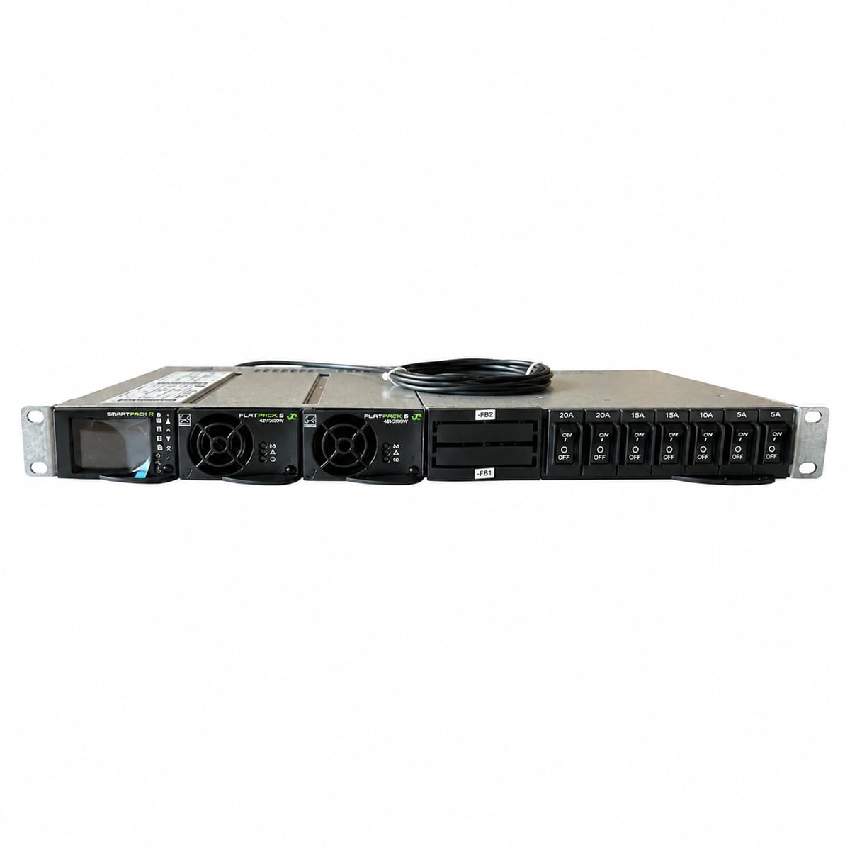
ELTEK CT0S0201 Embedded Telecom DC Power Subrack System (-48V 150A-300A / Flatpack2 & Smartpack) Official Studio Photo 3

Information below comes from the current product catalogue. Confirm the controller, software version and configuration of the installed equipment separately.

System Output Capacity
Max Supports 150A ~ 300A (-48V DC)
Rectifier Module Slots
Multi-Slot Supports Flatpack2 / Minipack Rectifiers
Monitoring Controller Configuration
Integrated Dedicated Smartpack Controller Slot
AC Distribution Input Spec
Single / 3-Phase Compatible AC Input Breaker
DC Distribution Branches
Multi-Channel DC Fuses & Low Voltage Disconnect (LVDS)
Physical Form Factor
Standard 19-inch Embedded Telecom Power Subrack

Alarms & troubleshooting

AC_MAINS_FAIL (AC Mains Failure / Phase Loss)
Controller Alarm LED solid RED; Rectifier AC Green LED OFF, Yellow/Red LED ON
Utility grid outage, AC input breaker tripped, or AC phase voltage below rectifier threshold (<85VAC)
1. Measure phase-to-neutral and neutral-to-earth voltages at the AC distribution box to verify grid status. 2. Inspect the subrack AC breaker/fuse positions; reset or replace after eliminating branch short circuits. 3. If input voltage is nominal (185-275VAC) but the rectifier remains offline, reseat or swap the rectifier module to identify backplane connector issues.
DC_HVSD (DC High Voltage Shutdown / Selective Lockout)
Faulty rectifier Alarm LED solid RED, Green LED OFF; Controller Critical Alarm active
Internal PWM loop control failure causing single module overvoltage, load-share loop corruption, or incorrect HVSD threshold setting in Smartpack
1. Access controller log to record the peak bus voltage and identify the specific rectifier slot that initiated HVSD. 2. Disconnect AC power to the faulty module and unseat it; wait until internal capacitors fully discharge. 3. Reseat the rectifier to test for soft-start recovery; if it instantly locks out with a red LED, replace the defective rectifier module.
LVBD_ACTIVE (Low Voltage Battery Disconnect Active)
Controller Alarm LED solid RED; Subrack DC distribution LVBD LED RED, audible buzzer active
Extended AC mains outage depleted battery capacity down to the disconnect threshold (e.g., 43.2V), tripping the contactor to prevent cell damage
1. Deploy mobile generator to restore subrack AC power; once rectifiers ramp up, LVBD contactor will auto-reconnect. 2. If AC power is restored but contactor stays open, verify the coil drive fuse and driver output signal on the Smartpack controller. 3. Execute manual contactor close command via controller GUI/keypad; if un responsive, check contactor auxiliary microswitches.
CAN_COMM_FAIL (CAN-bus Communication Timeout)
Controller Alarm LED solid YELLOW; Rectifier Green Power LED blinking, Yellow Warning LED ON
Loose subrack CAN-bus RJ45 patch cable, missing or damaged 120-ohm termination resistor, or a failed CAN transceiver in a rectifier pulling the bus low
1. Inspect subrack CAN interconnects and ensure the 120-ohm termination resistor plugs are firmly seated on both ends. 2. Power off or isolate the bus to measure resistance between CAN_H and CAN_L (should measure ~60 ohms with both terminators). 3. Reseat rectifiers one by one while monitoring controller status; the faulty module pulling the bus down is isolated when communications recover upon its extraction.
RECT_FAN_FAIL (Rectifier Fan Failure / Speed Tach Error)
Faulty rectifier Alarm LED blinking YELLOW or solid RED; Module output automatically derated to ~50%
Foreign object blocking the impeller, excessive dust accumulation seizing the bearing, or damaged internal fan Hall-effect tachometer circuit
1. Inspect the rectifier front intake grille and remove any foreign debris, dust mats, or airflow restrictions. 2. Hot-swap the module out of the subrack; spin the fan impeller manually to verify smooth rotation without bearing friction. 3. If the fan spins freely by hand but fails to spin up under electrical load, replace the fan assembly or swap the entire rectifier unit.

Access Complete Maintenance & Full Alarm Troubleshooting Manual

This page lists high-frequency critical alarm codes commonly encountered in field maintenance. Comprehensive manufacturer troubleshooting matrices, board-level repair guides, detailed electrical schematics, and firmware commissioning manuals are delivered alongside equipment upon formal project procurement, accompanied by dedicated FAE technical support.

Share on-site information

  1. 01

    Identify the exact model

    Record the nameplate, system model and controller or module model.

  2. 02

    Keep the alarm details

    Record the full alarm text, indicator colour, timing and whether it persists.

  3. 03

    Describe recent changes

    Note recent replacements, software updates or configuration changes.

Record information visible in the existing interface. Electrical measurements, disassembly and replacement should follow the applicable manufacturer's manual and be performed by qualified personnel.

Your model and these details will be added to the enquiry form for you to review before sending.

Related technical articles

Browse the technical guides or send a question about this model.

View all articles

Need a replacement module or supporting equipment?

Confirm the full model, system configuration and compatibility requirements before enquiring about suitable products.

Ask about suitable products

Have a model and an on-site issue?

Share the exact model, alarm text and observed symptoms to help identify relevant information and compatibility requirements.

Request technical support