Eltek / Site energy systems

Eltek Compact CT0S Equipment information & support

Eltek Compact CT0S is a shallow-depth embedded subrack system accommodating Flatpack2 rectifiers, Smartpack controller, and configurable breaker distribution.

Equipment information

Brand
Eltek
Equipment model
Eltek Compact CT0S
Equipment type
Site energy systems
Controller / software version
Confirm against the installed equipment
View full product specifications
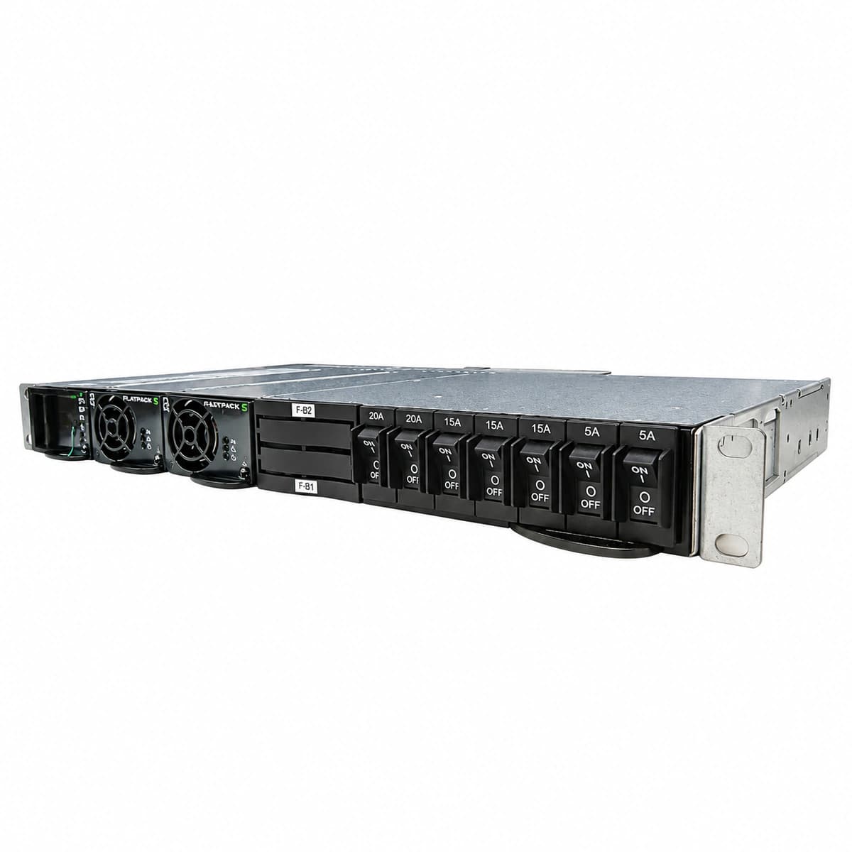
Eltek Compact CT0S Official Product View 1

Information below comes from the current product catalogue. Confirm the controller, software version and configuration of the installed equipment separately.

AC Input Voltage Range
85VAC ~ 300VAC VAC
Nominal DC Output Voltage
-48 V DC
Rectifier Module Slots
4 × Flatpack2 48/2000 or 48/3000 Slots
Physical Dimensions Spec
88 (2U) × 482 × 250 mm (shallow depth)
System Monitoring Controller
Smartpack S / Smartpack2

Alarms & troubleshooting

MAINS_FAIL (AC Mains Failure / Phase Loss)
Controller Alarm LED steady Red; Rectifier Power LED off, Warning LED blinking yellow
Commercial utility power failure, blown AC input fuse, tripped breaker, or AC phase voltage below 85VAC operating threshold
1. Measure true-RMS voltage between AC phase and neutral at the sub-distribution terminal (nominal range 185-275VAC). 2. Inspect the AC surge protection device (SPD) window status and check incoming miniature circuit breakers (MCBs). 3. Verify connection integrity and seating on the backplane AC power terminal blocks. 4. If AC grid is nominal, inspect rectifier rear plug-in connectors for thermal degradation or pin deformation.
RECT_HVSD (Rectifier Output High Voltage Shutdown)
Faulty Rectifier Alarm LED solid Red; Controller Critical Alarm LED on
Internal PWM loop failure, optocoupler feedback loss, or DC bus voltage exceeding the internal hardware protection threshold (typically 59.5VDC)
1. Unlatch and pull out the faulty rectifier; wait 2 minutes for bulk capacitor discharge, then reseat to reset latch. 2. If HVSD re-trips immediately, measure system bus voltage and verify controller 'HVSD Setpoint' configuration. 3. Identify the faulty module serial number via controller GUI/display, tag it, and replace with a validated spare. 4. Check load share calibration across remaining active modules to prevent systemic bus voltage creep.
CAN_COMM_FAIL (CAN-Bus Communication Failure)
Controller Alarm LED steady Yellow; Rectifier Warning LEDs flashing yellow, modules operating in standalone/fail-safe mode
Backplane CAN bus signal line open/short, missing 120-ohm termination resistor, unseated Smartpack controller, or faulty CAN transceiver dragging down bus differential voltage
1. Inspect controller backplane connector engagement; reseat the Smartpack unit and tighten retention screws. 2. Disconnect AC/DC auxiliary power and measure resistance between CAN-H and CAN-L across the bus (nominal: ~60 ohms for dual 120-ohm terminations). 3. Sequentially unseat rectifiers one-by-one while monitoring controller status to isolate any module clamping the bus. 4. Check multi-shelf ribbon cables and CAN terminating jumpers on the CT0S distribution board for pin damage.
BATT_LVBD (Low Voltage Battery Disconnect Active)
Controller Critical LED solid Red; LVBD latching contactor physically open
Prolonged mains outage exhausted battery reserve; string voltage dropped below configured safety threshold (typically 43.2VDC for 48V bank), prompting controller to trip LVBD contactor to prevent cell reversal
1. Restore AC utility mains or deploy mobile generator to bring rectifiers online and re-energize the DC bus. 2. Verify rectifier output voltage exceeds the LVBD reconnect threshold (typically >48.0VDC) and watch for automatic latch reclosure. 3. If rectifiers are live but contactor stays open, navigate to controller Maintenance menu and manually issue 'LVBD Close' command. 4. Measure pulse voltage on the contactor driver coil terminal on the CT0S interface card; verify auxiliary microswitch feedback.
RECT_OVERTEMP (Rectifier Thermal Derating / Over-Temperature Trip)
Affected rectifier Warning LED solid Yellow (derating) or Alarm LED flashing Red (thermal trip); Controller Minor/Major Alarm active
Clogged cabinet air intake dust filters, ambient HVAC failure causing intake air to exceed 55°C, integrated brushless cooling fan speed degradation, or restricted rear exhaust plenum
1. Inspect front intake mesh and remove particulate clogging to restore design CFM airflow. 2. Query the internal heatsink temperature telemetry via the controller (nominal operational threshold is <85°C internal). 3. Visually check the front cooling fan impeller for physical obstruction or bearing seizure; verify PWM speed feedback. 4. If intake ambient is within spec (<45°C) and airflow is clear but fan does not spin up, replace the modular fan assembly or swap the rectifier.

Access Complete Maintenance & Full Alarm Troubleshooting Manual

This page lists high-frequency critical alarm codes commonly encountered in field maintenance. Comprehensive manufacturer troubleshooting matrices, board-level repair guides, detailed electrical schematics, and firmware commissioning manuals are delivered alongside equipment upon formal project procurement, accompanied by dedicated FAE technical support.

Share on-site information

  1. 01

    Identify the exact model

    Record the nameplate, system model and controller or module model.

  2. 02

    Keep the alarm details

    Record the full alarm text, indicator colour, timing and whether it persists.

  3. 03

    Describe recent changes

    Note recent replacements, software updates or configuration changes.

Record information visible in the existing interface. Electrical measurements, disassembly and replacement should follow the applicable manufacturer's manual and be performed by qualified personnel.

Your model and these details will be added to the enquiry form for you to review before sending.

Related technical articles

Browse the technical guides or send a question about this model.

View all articles

Need a replacement module or supporting equipment?

Confirm the full model, system configuration and compatibility requirements before enquiring about suitable products.

Ask about suitable products

Have a model and an on-site issue?

Share the exact model, alarm text and observed symptoms to help identify relevant information and compatibility requirements.

Request technical support