Eltek / DC power systems

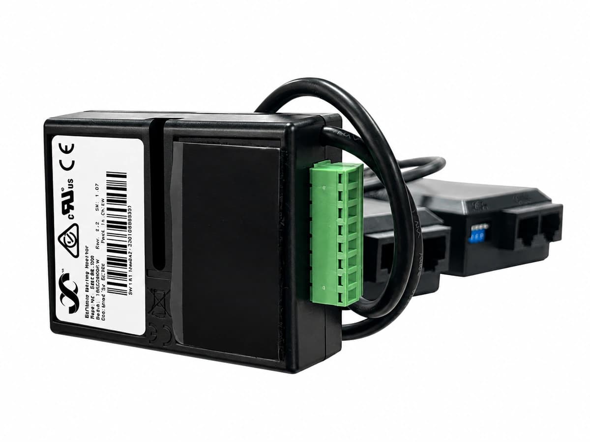
Eltek Battery String Monitor (242100.300) Equipment information & support

Precision battery monitoring unit for Eltek DC systems, sampling midpoint voltages, battery temperatures, and detecting early battery degradation.

Equipment information

Brand
Eltek
Equipment model
Eltek Battery String Monitor (242100.300)
Equipment type
DC power systems
Controller / software version
Confirm against the installed equipment
View full product specifications
Eltek Battery String Monitor (242100.300) authentic hardware perspective 3

Information below comes from the current product catalogue. Confirm the controller, software version and configuration of the installed equipment separately.

Battery Monitoring Capacity
Monitors up to 4 battery strings (midpoint voltage & temp)
Sampling Precision (V & T)
Voltage accuracy ±0.1%, temperature accuracy ±0.5°C
Industrial Telemetry Bus
Standard industrial CAN bus direct to Smartpack
Galvanic Voltage Isolation
2500V DC galvanic opto-isolation protection
Internal Power Consumption
Ultra-low power < 2W (powered by CAN or DC bus)
Official Part Number
242100.300 (Official Battery String Monitor PN)

Alarms & troubleshooting

CAN_COMM_FAIL (CAN-bus Communication Failure)
Power LED Green solid, Alarm LED Amber/Red flashing at 1Hz
Damaged/loose RJ45 CAN-bus patch cord between BSM and Smartpack controller, missing 120-ohm termination resistor, or CAN transceiver fault.
1. Verify continuity of RJ45 cables and connectors between BSM and Smartpack controller. 2. Measure CAN-bus loop impedance (nominal ~60 ohms powered down). 3. Access Smartpack Web/PowerSuite interface, review CAN device list, and initiate node scan. 4. If unresolved, replace BSM module (242100.300) and reconfigure.
BATT_SYM_DEV (Battery Symmetry Voltage Deviation)
Alarm LED Red solid, Power LED Green solid
Midpoint voltage deviates from half-string potential beyond configured threshold (e.g., >0.5V-1.0V), indicating degraded block, unequal self-discharge, or loose sensing wire.
1. Measure individual block voltages using a calibrated DMM to isolate degraded monoblocs. 2. Inspect and torque symmetry sense wiring connections at terminal posts. 3. Initiate an equalization charge cycle to rebalance cells. 4. Conduct internal resistance/conductance test; replace failed battery blocks.
CELL_VOLT_LOW (Battery Cell/Block Under-Voltage)
Alarm LED Red solid, system buzzer active (if enabled)
Deep discharge condition during prolonged outage, internal short circuit of battery cell, open-circuit sensing wire, or blown inline fuse on sense cable.
1. Inspect BSM sensing wire harness and inline fuses; measure actual terminal voltage with a calibrated meter. 2. If system is discharging, start backup generator to restore rectifier charging and prevent LVD disconnect. 3. If under float charge, inspect block for thermal swelling or leakage; replace defective unit. 4. Verify BSM voltage calibration via Smartpack.
BATT_TEMP_HIGH (Battery High Temperature / Sensor Fault)
Alarm LED Red flashing at 2Hz, Power LED Green solid
HVAC failure causing elevated ambient room temperature, thermal runaway risk during recharge, or damaged/shorted NTC temperature probe yielding false high reading (>50°C).
1. Cross-check physical battery temperature with an infrared thermal camera. 2. Verify DC system temp compensation and inspect room HVAC operation. 3. Disconnect probe and measure NTC resistance curve; replace faulty sensor cable. 4. If actual thermal runaway is detected, immediately reduce float voltage or isolate string to prevent fire.
CURR_SENS_FAIL (Current Sensor / Shunt Signal Fault)
Alarm LED Amber solid, Power LED Green solid
Broken or reversed mV shunt sense wiring, auxiliary power loss to Hall-effect current transducer, or incorrect shunt rating configuration in Smartpack.
1. Measure actual battery string current with a calibrated DC clamp meter and compare with BSM readout. 2. Verify mV wiring polarity and continuity between shunt and BSM current input terminals. 3. Check auxiliary power supply to Hall sensor if applicable. 4. Re-calibrate zero current offset and confirm shunt rating settings in Smartpack controller.

Access Complete Maintenance & Full Alarm Troubleshooting Manual

This page lists high-frequency critical alarm codes commonly encountered in field maintenance. Comprehensive manufacturer troubleshooting matrices, board-level repair guides, detailed electrical schematics, and firmware commissioning manuals are delivered alongside equipment upon formal project procurement, accompanied by dedicated FAE technical support.

Share on-site information

  1. 01

    Identify the exact model

    Record the nameplate, system model and controller or module model.

  2. 02

    Keep the alarm details

    Record the full alarm text, indicator colour, timing and whether it persists.

  3. 03

    Describe recent changes

    Note recent replacements, software updates or configuration changes.

Record information visible in the existing interface. Electrical measurements, disassembly and replacement should follow the applicable manufacturer's manual and be performed by qualified personnel.

Your model and these details will be added to the enquiry form for you to review before sending.

Related technical articles

Browse the technical guides or send a question about this model.

View all articles

Need a replacement module or supporting equipment?

Confirm the full model, system configuration and compatibility requirements before enquiring about suitable products.

Ask about suitable products

Have a model and an on-site issue?

Share the exact model, alarm text and observed symptoms to help identify relevant information and compatibility requirements.

Request technical support